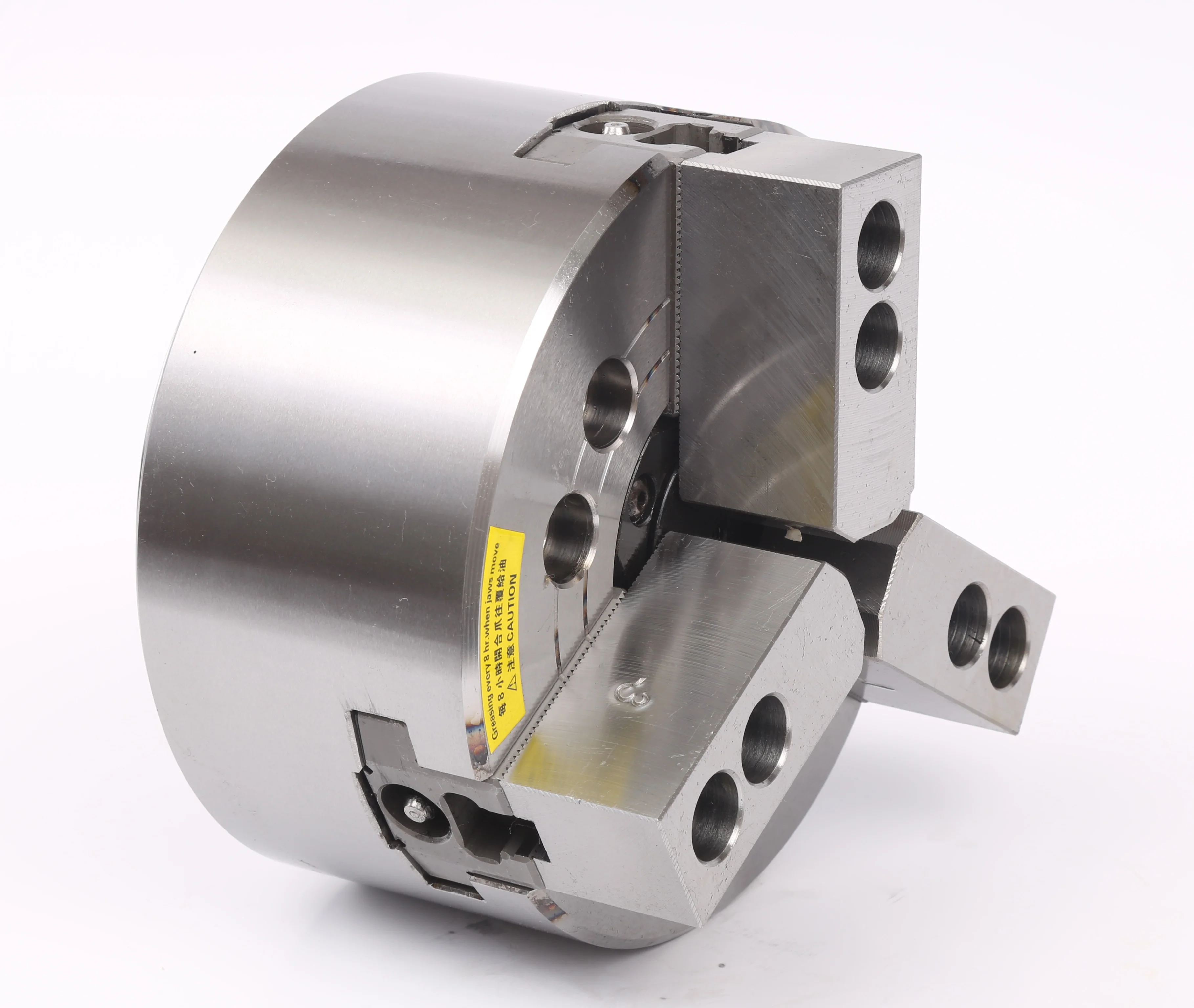
3-Jaw Hollow Hydraulic Chuck
A common hydraulic chuck for round workpieces and batch turning. Confirm through-hole size, drawbar, rotary cylinder, spindle nose and clamping range.
Hydraulic lathe chucks for CNC turning, automated clamping and stable production cycles.
KORRETTO hydraulic chucks are used with rotary hydraulic cylinders and drawbars to provide controlled clamping and release on CNC lathes. This series includes 3-jaw hollow hydraulic chucks, 3-jaw solid hydraulic chucks, 2-jaw hollow hydraulic chucks, 4-jaw hollow hydraulic chucks, rotary hydraulic cylinders, soft jaws and hard jaws. They are suitable for batch turning, automation and applications that require repeatable clamping force and stable cycle timing.
Select a hydraulic chuck by jaw number, through-hole requirement, workpiece shape, spindle nose, drawbar stroke, rotary cylinder and clamping force. Hollow hydraulic chucks are used when bar stock or tubing must pass through the spindle; solid hydraulic chucks are used when through-spindle material feeding is not required.
A common hydraulic chuck for round workpieces and batch turning. Confirm through-hole size, drawbar, rotary cylinder, spindle nose and clamping range.
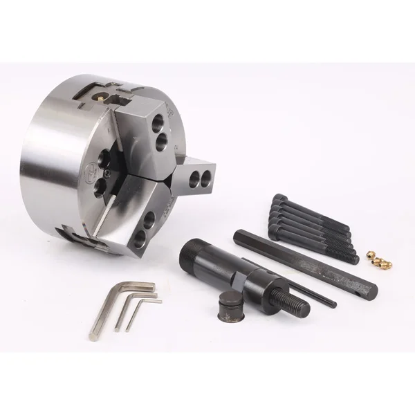
Suitable when the workpiece does not need to pass through the spindle. Check spindle nose, drawbar, solid rotary cylinder, clamping range and speed.
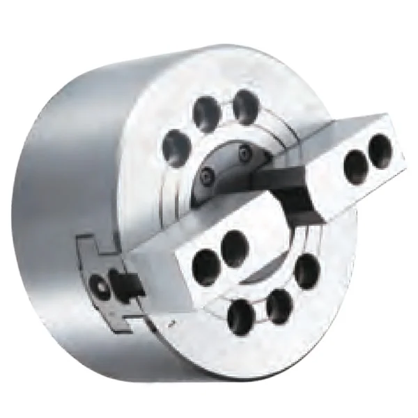
Used when a standard 3-jaw hydraulic chuck cannot contact the workpiece correctly. Hollow construction supports bar or tube passage when required.

Suitable for workpieces that benefit from four-point support and through-spindle passage. Confirm workpiece shape, through hole, drawbar, rotary cylinder and cutting load.
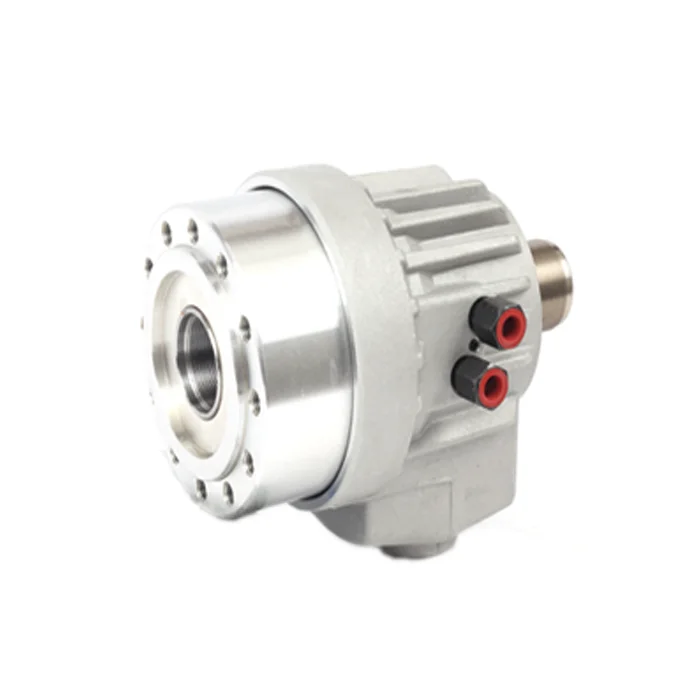
The rotary cylinder drives the chuck through the drawbar. Hollow cylinders support bar passage; solid cylinders are used where through-spindle feeding is not required.
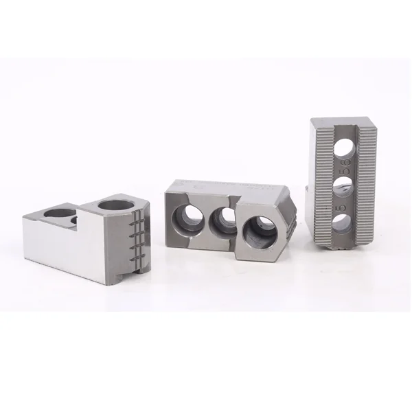
Soft jaws are often machined to match the workpiece profile for repeat production. Hard jaws are used when jaw rigidity and durability are more important.
Send the workpiece drawing, machine model, spindle nose, drawbar thread, drawbar stroke, rotary cylinder information and target clamping force. We can help compare 3-jaw, 2-jaw, 4-jaw, hollow, solid and rotary cylinder options.
Submit Your Project- CNC lathe production with repeated clamping cycles.
- Automated loading or program-controlled clamping.
- Applications requiring more consistent clamping force than manual tightening.
- Machines already equipped for hydraulic actuation and suitable filtration.
- Prototype or repair work with low cycle pressure: check Manual Chucks.
- Clean-air environments where hydraulic oil is restricted: check Pneumatic Chucks.
- Thin-wall or deformation-sensitive parts: check Collet Chucks, Diaphragm Chucks, Rubber-Flex Collets or 6-Jaw Chucks.
- Special workpieces requiring pull-down, face clamping or pipe-thread clamping: check Special Hydraulic Chucks.
| Requirement | Start with |
|---|---|
| General round parts and batch CNC turning | 3-Jaw Hollow Hydraulic Chuck or 3-Jaw Solid Hydraulic Chuck |
| Bar stock or tube passing through the spindle | Hollow Hydraulic Chuck |
| Short blanks without through-spindle feeding | Solid Hydraulic Chuck |
| Symmetrical shaped parts or custom jaw profiles | 2-Jaw Hollow Hydraulic Chuck |
| Square or four-sided parts requiring four-point clamping | 4-Jaw Hollow Hydraulic Chuck |
| Unknown drawbar force or stroke | Rotary Hydraulic Cylinder and drawbar review |
| Profile-matched production clamping | Soft Jaws |
| Interrupted or heavier cutting | Hard Jaws or a stronger chuck/cylinder combination |
| Requirement | Related solution |
|---|---|
| Small-batch, repair or wrench-operated workholding | Manual Chucks |
| Clean compressed-air clamping | Pneumatic Chucks |
| Thin-wall or deformation-sensitive round parts | Collet Chucks / Diaphragm Chucks / Rubber-Flex Collets / 6-Jaw Chucks |
| Internal bore location | Expanding Mandrels |
| Pull-down, ball-joint, face-clamping or pipe-thread workholding | Special Hydraulic Chucks |
| Indexed or multi-angle operations | Indexing Chucks / Rotary Tables |
Not always. In lathe workholding, some customers use the terms loosely, but a hydraulic chuck usually refers to a jaw-type chuck driven by a rotary hydraulic cylinder and drawbar. A hydraulic collet chuck uses a different clamping mechanism and must be selected separately.
A hydraulic chuck uses a cylinder and drawbar to clamp and release through the machine control. It is better for repeated production and automated cycles. A manual chuck is tightened with a wrench and is often simpler for repair work, trials and small batches.
Provide the spindle nose, drawbar thread, drawbar stroke, required clamping force, maximum speed and whether a hollow or solid system is required. The chuck, cylinder and drawbar must be checked as a complete clamping system.
Choose a hollow hydraulic chuck when bar stock or tubing must pass through the spindle. Choose a solid hydraulic chuck when the workpiece is short and through-spindle feeding is not required.
It depends on wall thickness, material, jaw contact and cutting conditions. For deformation-sensitive parts, collet chucks, diaphragm chucks, rubber-flex collets or 6-jaw chucks should also be reviewed before final selection.
Send the workpiece drawing, material, machine model, spindle nose, drawbar information, rotary cylinder model, target speed, cutting load and current clamping issue.