Two-jaw through-hole hydraulic chuck for shaped parts, custom jaws and symmetrical workpieces.
2-Jaw Hollow Hydraulic Chuck
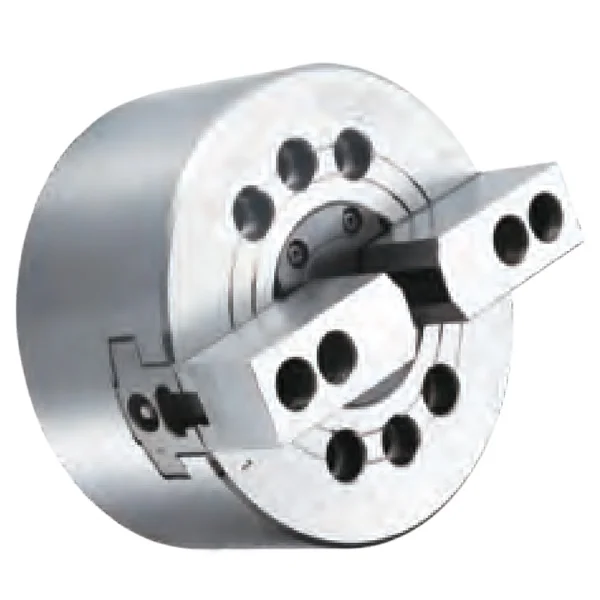
KORRETTO 2-jaw hollow hydraulic chuck is designed for workpieces that cannot be held correctly by a standard 3-jaw chuck. It is suitable for symmetrical shaped parts, square or rectangular profiles, custom soft jaws and applications where two-point clamping is more appropriate. The hollow structure supports through-spindle passage when bar or tube clearance is required.
Product Overview
The 2-jaw hollow hydraulic chuck uses synchronized two-jaw clamping and is often selected together with custom jaws. It is useful when the workpiece profile requires two opposing contact areas rather than three-point clamping.
This page only covers the 2-jaw hollow hydraulic chuck. No confirmed 2-jaw solid hydraulic chuck data is included in this page.
Key Features
| Feature | Description |
|---|---|
| 2-jaw synchronized clamping | Suitable for symmetrical shaped parts and custom jaw designs. |
| Hollow structure | Allows through-spindle clearance when the workpiece or material requires it. |
| Custom jaw compatibility | Can be used with formed soft jaws or special jaws based on the workpiece shape. |
| CNC lathe hydraulic actuation | Works with compatible rotary hydraulic cylinder and drawbar setup. |
| Alternative to 3-jaw clamping | Used when a standard 3-jaw hydraulic chuck cannot contact the part correctly. |
Typical Applications
- Symmetrical shaped components
- Square or rectangular parts
- Special profiles requiring custom jaws
- Workpieces needing two-point clamping
- CNC lathe jobs requiring through-hole clearance
Technical Data and Dimensions
Use the drawing and parameter table to check chuck size, through-hole diameter, jaw stroke, mounting dimensions, clamping force, speed and compatible machine conditions.
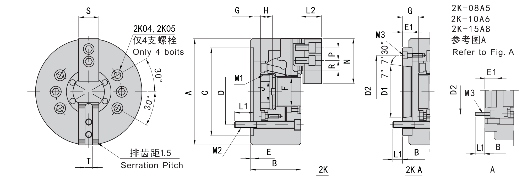
Use this drawing to confirm main dimensions, jaw stroke and through-hole details.
| Model | Spindle Nose | A | B | C (H6) | D | D1 | D2 | E | E1 | F | G max | G min | H | J |
|---|---|---|---|---|---|---|---|---|---|---|---|---|---|---|
| 2K-04 | 110 | 59 | 85 | 70.6 | 4 | 26 | 3.5 | -6.5 | 17.5 | 12 | ||||
| 2K-05 | A4 | 135 | 60 / 71 | 110 | 82.6 | 63.51 | 96 | 4 | 15 | 45 | 26 | -1 / 14 | 20 | 12 |
| 2K-06 | A5 | 169 | 81 / 91 | 140 | 104.8 | 82.56 | 116 | 5 | 23 | 1 | 16 | -9 / 6 | 19 | 20 |
| 2K-08 | A5 | 210 | 91 / 109 | 170 | 133.4 | 82.56 | 104.8 | 5 | 23 | 52 | 37.5 | -1.5 / 21.5 | 20.5 | 30 |
| 2K-08 | A6 | 210 | 91 / 103 | 170 | 133.4 | 106.38 | 150 | 5 | 17 | 52 | 31.5 | -1.5 / 15.5 | 20.5 | 30 |
| 2K-10 | A6 | 254 | 100 / 120 | 220 | 171.4 | 106.38 | 133.4 | 5 | 25 | 75 | 33.5 | -10.5 / 14.5 | 25 | 45 |
| 2K-10 | A8 | 254 | 100 / 113 | 220 | 171.4 | 139.72 | 190 | 5 | 18 | 75 | 26.5 | -10.5 / 7.5 | 25 | 45 |
| 2K-12 | A8 | 304 | 110 / 122 | 220 | 171.4 | 139.72 | 190 | 6 | 18 | 91 | 26 | -15 / 3 | 28 | 50 |
| 2K-15 | A8 | 381 | 133 / 160 | 300 | 235 | 171.4 | 171.4 | 6 | 33 | 120 | 44 | -12 / 21 | 39 | 60 |
| 2K-15 | A11 | 381 | 133 / 149 | 300 | 235 | 196.87 | 260 | 6 | 22 | 120 | 33 | -12 / 10 | 39 | 60 |
| 2K-18 | A11 | 450 | 110 | 300 | 235 | 196.87 | 260 | 6 | 22 | 120 | 33 | -12 / 10 | 39 | 60 |
| Model | Spindle Nose | Plunger Stroke (mm) | Jaw Stroke (Diameter, mm) | Max. Pull kN (kgf) | Max. Clamping kN (kgf) | Max. Speed (r/min) | Clamping Range (mm) | Moment of Inertia (kg·m²) | Weight (kg) | Matching Cylinder | Max. Pressure MPa (kgf/cm²) |
|---|---|---|---|---|---|---|---|---|---|---|---|
| 2K-04 | 10 | 5.4 | 13.7(1400) | 28.4(2900) | 8000 | 7-110 | 0.01 | 4 | 428 | 2.1 | |
| 2K-05 | A4 | 10 | 5.4 | 17.1(1750) | 35.8(3650) | 7000 | 12-135 | 0.02 | 6.7 / 7.5 | 536 | 2.6 |
| 2K-06 | A5 | 12 | 5.5 | 21.5(2200) | 56.8(5800) | 6000 | 15-168 | 0.06 | 11.9 / 13.7 | 646 | 2.5 |
| 2K-08 | A5 | 16 | 7.4 | 34.3(3500) | 85.8(8750) | 5000 | 13-210 | 0.18 | 22.5 / 25.4 | 852 | 2.8 |
| 2K-08 | A6 | 16 | 7.4 | 34.3(3500) | 85.8(8750) | 5000 | 13-210 | 0.18 | 22.5 / 23.6 | 852 | 2.8 |
| 2K-10 | A6 | 19 | 8.8 | 42.6(4380) | 110.7(11300) | 4200 | 31-254 | 0.33 | 34.5 / 41.65 | 1075 | 2.6 |
| 2K-10 | A8 | 19 | 8.8 | 42.6(4380) | 110.7(11300) | 4200 | 31-254 | 0.33 | 34.5 / 40 | 1075 | 2.6 |
| 2K-12 | A8 | 23 | 10.6 | 54.9(5600) | 143.6(14650) | 3300 | 34-304 | 0.77 | 56.6 / 59.5 | 1291 | 2.6 |
| 2K-15 | A8 | 23 | 10.6 | 71(7250) | 179.8(18350) | 2500 | 50-381 | 2.47 | 120 / 134 | 1512 | 2.4 |
| 2K-15 | A11 | 23 | 10.6 | 71(7250) | 179.8(18350) | 2500 | 50-381 | 2.39 | 120 / 127 | 1512 | 2.4 |
| 2K-18 | A11 | 23 | 10.6 | 71(7250) | 179.8(18350) | 2000 | 50-450 | 4.78 | 164 / 178 | 1512 | 2.4 |
FAQ
When should I use a 2-jaw hydraulic chuck?
Use a 2-jaw hydraulic chuck when the workpiece is symmetrical but not suitable for standard 3-jaw clamping, or when custom jaws need to grip two opposing surfaces.
Is this page for hollow or solid 2-jaw hydraulic chucks?
This page is only for the 2-jaw hollow hydraulic chuck. It does not include solid 2-jaw hydraulic chuck data.
Can this chuck use custom soft jaws?
Yes. 2-jaw hydraulic chucks are often used with soft jaws or formed jaws machined to the workpiece profile.
What should be checked before selection?
Check the workpiece shape, jaw contact area, through-hole requirement, spindle nose, drawbar stroke, cylinder thrust, jaw stroke and maximum speed.
Is a 2-jaw hydraulic chuck suitable for round parts?
It can hold some round parts with suitable jaws, but standard round workpieces are usually first evaluated with a 3-jaw hydraulic chuck.