Hollow and solid rotary hydraulic cylinders for CNC lathe hydraulic chuck actuation.
Rotary Hydraulic Cylinder
KORRETTO rotary hydraulic cylinders drive hydraulic chuck clamping and release through the drawbar on CNC lathes. This page covers both hollow rotary hydraulic cylinders and solid rotary hydraulic cylinders. Hollow cylinders are used when bar stock or tube stock must pass through the spindle, while solid cylinders are used when through-spindle feeding is not required.
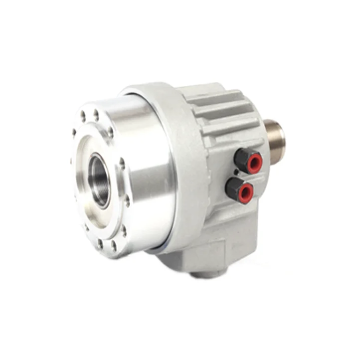
Product Overview
A rotary hydraulic cylinder is the actuator that provides the thrust and stroke needed to clamp and release a hydraulic chuck. It must be selected together with the chuck, drawbar, spindle nose and hydraulic system.
This page is a combined page for hollow and solid rotary hydraulic cylinders. The two types must be displayed in separate sections so users can clearly see which drawing and parameter table belong to which cylinder type.
Product Types
| Type | Description | Typical use |
|---|---|---|
| Hollow Rotary Hydraulic Cylinder | Rotary cylinder with through-hole structure. | Bar stock, tube stock and machines requiring through-spindle material passage. |
| Solid Rotary Hydraulic Cylinder | Rotary cylinder without through-hole passage. | Short workpieces, individual blanks and solid chuck systems. |
Technical Data and Dimensions
Do not place all parameter tables continuously. Each cylinder type must have its own product image, drawing and parameter table group.
Hollow Rotary Hydraulic Cylinder
Hollow rotary hydraulic cylinder for through-spindle bar or tube work.
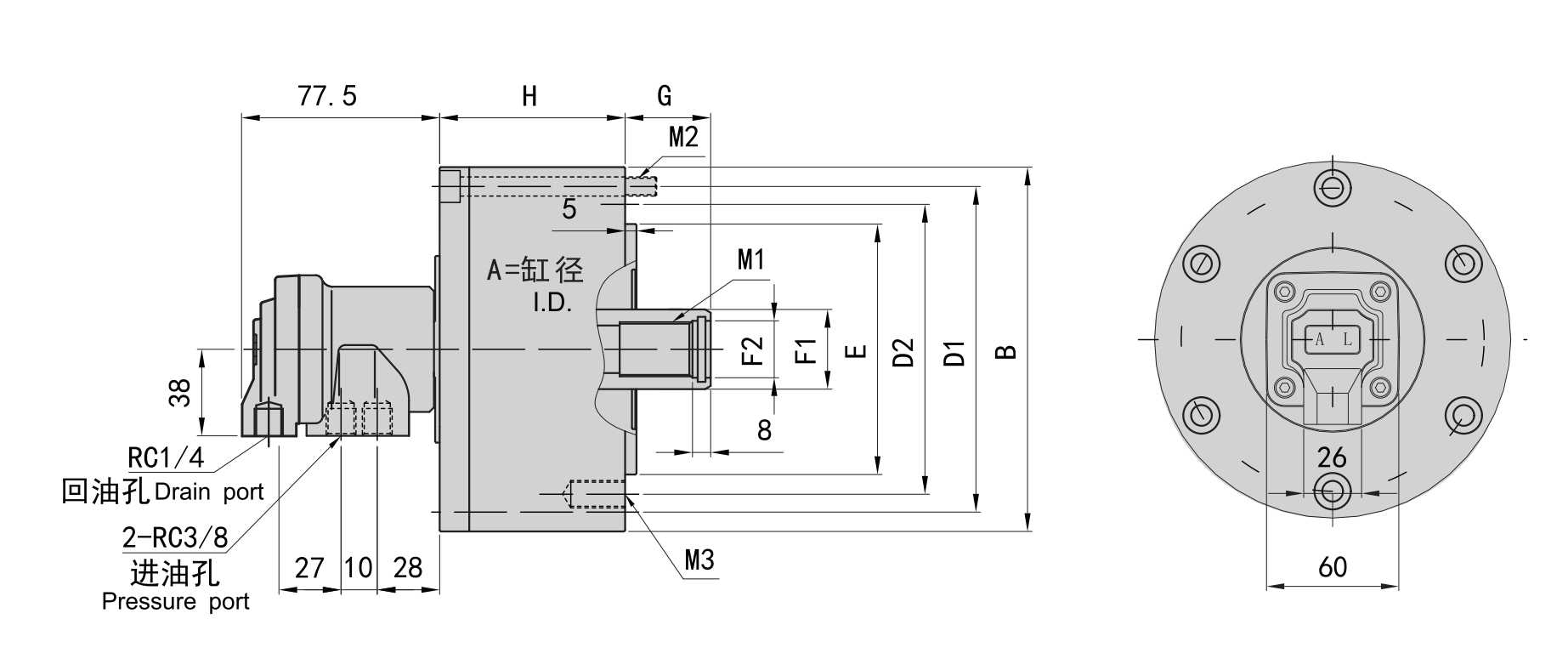
Use this drawing to confirm the hollow cylinder dimensions and drawbar connection.
| Model | A (Piston Diameter) | B | D1 | D2 | E(H7) | F1 | F2(H8) | G1 max | G1 min | G2 max | G2 min | H | J | K | L1 | L2 | M1 | M2 |
|---|---|---|---|---|---|---|---|---|---|---|---|---|---|---|---|---|---|---|
| KY-428T | 90 | 124 | 100 | 108 | 80 | 40 | 30 | 10 | 0 | 35 | 25 | 61 | 94.5 | 139 | 25 | 13 | M33*1.5 | 6-M8*65 |
| KY-532T | 105 | 141 | 115 | 125 | 100 | 48 | 35 | 15 | 0 | 40 | 25 | 70 | 107.5 | 148 | 25 | 13 | M38*1.5 | 6-M8*75 |
| KY-536T | 105 | 141 | 115 | 125 | 100 | 48 | 38 | 15 | 0 | 40 | 25 | 70 | 107.5 | 148 | 25 | 13 | M42*1.5 | 6-M8*75 |
| KY-642T | 125 | 156 | 130 | 140 | 100 | 65 | 45 | 15 | 0 | 40 | 25 | 76 | 107.5 | 148 | 30 | 16 | M50*2 | 6-M8*75 |
| KY-646T | 125 | 156 | 130 | 140 | 100 | 65 | 50 | 15 | 0 | 40 | 25 | 76 | 107.5 | 148 | 30 | 16 | M55*2 | 6-M8*75 |
| KY-846T | 145 | 185 | 170 | 165 | 130 | 70 | 50 | 20 | 0 | 45 | 25 | 72 | 150 | 30 | 16 | M55*2 | 6-M10*100 | |
| KY-852T | 145 | 185 | 170 | 165 | 130 | 70 | 55 | 20 | 0 | 45 | 25 | 72 | 150 | 30 | 16 | M60*2 | 6-M10*100 | |
| KY-1068T | 175 | 215 | 190 | 190 | 160 | 95 | 70 | 25 | 0 | 50 | 25 | 94 | 136 | 188 | 35 | 16 | M75*2 | 6-M10*100 |
| KY-1075T | 175 | 215 | 190 | 190 | 160 | 95 | 80 | 25 | 0 | 50 | 25 | 94 | 136 | 188 | 35 | 16 | M85*2 | 6-M10*100 |
| KY-1287T | 205 | 240 | 215 | 220 | 180 | 110 | 90 | 30 | 0 | 55 | 30 | 100 | 145 | 205 | 35 | 16 | M95*2 | 6-M10*105 |
| KY-1291T | 205 | 240 | 215 | 220 | 180 | 110 | 95 | 30 | 0 | 55 | 30 | 100 | 145 | 205 | 35 | 16 | M100*2 | 6-M10*105 |
| KY-1512T | 250 | 305 | 275 | 280 | 230 | 140 | 115 | 30 | 0 | 55 | 30 | 113 | 156 | 245 | 35 | 16 | M120*2 | 6-M12*120 |
| Model | Push-Side Piston Area (cm²) | Pull-Side Piston Area (cm²) | Piston Stroke (mm) | Max. Speed (r/min) | Max. Pressure MPa (kgf/cm²) | Max. Push-Side Force kN (kgf) | Max. Pull-Side Force kN (kgf) | Moment of Inertia (kg·m²) | Weight (kg) | Total Leakage L/min |
|---|---|---|---|---|---|---|---|---|---|---|
| KY-428T | 51.9 | 51 | 10 | 7000 | 40(4.0) | 1868(18.3) | 1836(18) | 0.1 | 5.8 | 2.6 |
| KY-532T | 70.8 | 68.5 | 15 | 6000 | 40(4.0) | 2548(25) | 2466(24.2) | 0.012 | 6.1 | 3 |
| KY-536T | 70.8 | 68.5 | 15 | 6000 | 40(4.0) | 2548(25) | 2466(24.2) | 0.012 | 6.1 | 3 |
| KY-642T | 99.1 | 88 | 15 | 6000 | 40(4.0) | 3567(35) | 3168(31) | 0.018 | 6.1 | 3 |
| KY-646T | 99.1 | 88 | 15 | 6000 | 40(4.0) | 3567(35) | 3168(31) | 0.018 | 6.1 | 3 |
| KY-846T | 135.3 | 125 | 20 | 5500 | 40(4.0) | 4870(47.7) | 4500(44.1) | 0.035 | 11.8 | 3.9 |
| KY-852T | 135.3 | 125 | 20 | 5500 | 40(4.0) | 4870(47.7) | 4500(44.1) | 0.035 | 11.8 | 3.9 |
| KY-1068T | 182.7 | 169.5 | 25 | 4500 | 40(4.0) | 6577(64.5) | 6102(59.8) | 0.08 | 17.8 | 4.2 |
| KY-1075T | 182.7 | 169.5 | 25 | 4500 | 40(4.0) | 6577(64.5) | 6102(59.8) | 0.08 | 17 | 4.2 |
| KY-1287T | 249.3 | 232.8 | 30 | 3800 | 40(4.0) | 8975(87.9) | 8380(82.1) | 0.11 | 26.5 | 4.5 |
| KY-1291T | 249.3 | 232.8 | 30 | 3800 | 40(4.0) | 8975(87.9) | 8380(82.1) | 0.11 | 24.8 | 4.5 |
| KY-1511T | 356.5 | 335.3 | 30 | 3000 | 40(4.0) | 12830(125.7) | 12070(118.3) | 0.38 | 56.6 | 7.0 |
| KY-1512T | 356.5 | 335.3 | 30 | 3000 | 40(4.0) | 12830(125.7) | 12070(118.3) | 0.38 | 49.5 | 7.0 |
Solid Rotary Hydraulic Cylinder
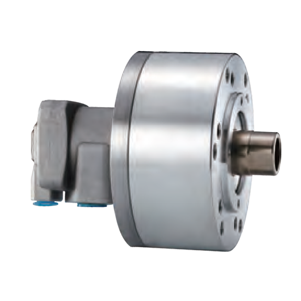
Solid rotary hydraulic cylinder for non-through-spindle clamping systems.
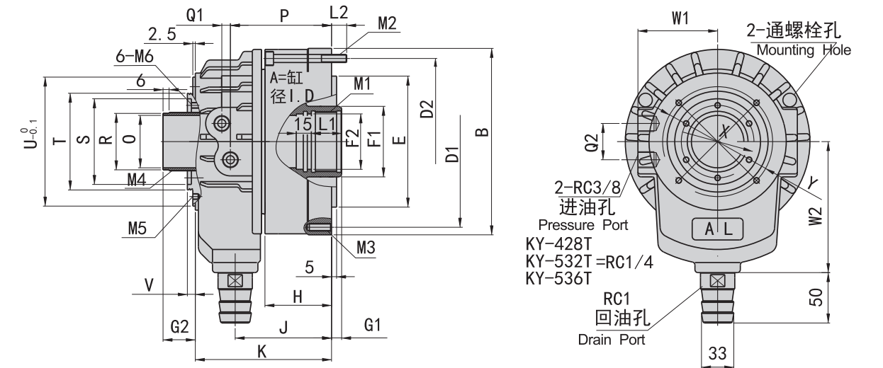
Use this drawing to confirm the solid cylinder dimensions and mounting details.
| Model | A | B | D1 | D2 | E(H7) | F1 | F2(H8) | G max | G min | H | M1 | M2 | M3 |
|---|---|---|---|---|---|---|---|---|---|---|---|---|---|
| SY-75H | 75 | 107 | 90 | 90 | 65 | 28 | 21 | 45 | 30 | 60 | M20*35 | M8*60 | 6-M8*16 |
| SY-100H | 100 | 135 | 115 | 100 | 80 | 28 | 21 | 45 | 25 | 77 | M20*35 | M8*75 | 6-M10*20 |
| SY-125H | 125 | 160 | 140 | 130 | 110 | 35 | 25 | 50 | 25 | 85 | M24*40 | M8*85 | 6-M12*20 |
| SY-150H | 150 | 190 | 170 | 130 | 110 | 45 | 31 | 55 | 25 | 98 | M30*45 | M10*100 | 12-M12*24 |
| SY-200H | 200 | 245 | 220 | 145 | 120 | 55 | 37 | 70 | 35 | 118 | M36*60 | M10*125 | 12-M16*30 |
| SY-250H | 250 | 296 | 275 | 200 | 160 | 60 | 37 | 100 | 40 | 156 | M36*60 | M12*160 | 12-M20*30 |
| Model | Push-Side Piston Area (cm²) | Pull-Side Piston Area (cm²) | Piston Stroke (mm) | Max. Speed (r/min) | Max. Pressure MPa (kgf/cm²) | Max. Push-Side Force kN (kgf) | Max. Pull-Side Force kN (kgf) | Moment of Inertia (kg·m²) | Weight (kg) |
|---|---|---|---|---|---|---|---|---|---|
| SY-75H | 41.7 | 37 | 15 | 6000 | 40(4.0) | 1500(14.7) | 1330(13) | 0.02 | 3.2 |
| SY-100H | 75.4 | 70.8 | 20 | 5000 | 40(4.0) | 2710(26.6) | 2550(25) | 0.04 | 4.8 |
| SY-125H | 119.6 | 111.5 | 25 | 5000 | 40(4.0) | 4300(42.1) | 4010(39.3) | 0.06 | 7.2 |
| SY-150H | 173.6 | 159.2 | 30 | 5000 | 40(4.0) | 6250(61.2) | 5730(56.2) | 0.1 | 9.8 |
| SY-200H | 314.1 | 290.4 | 35 | 4000 | 40(4.0) | 11300(110.8) | 10454(102.4) | 0.25 | 15.7 |
| SY-250H | 485.7 | 462.3 | 60 | 2000 | 40(4.0) | 17500(171.5) | 16640(163.0) | 0.52 | 45.5 |
Selection Notes
- Choose hollow type when through-spindle passage is required.
- Choose solid type when the workpiece is short and through-spindle feeding is not needed.
- Match cylinder thrust and stroke with the chuck.
- Confirm drawbar thread, drawbar length and mounting dimensions.
- Check maximum speed, pressure range and hydraulic system compatibility.
- Review safety interlock and pressure stability for automated clamping.
FAQ
What does a rotary hydraulic cylinder do?
It provides the thrust and stroke needed to clamp and release a hydraulic chuck through the drawbar while the spindle rotates.
What is the difference between a hollow and solid rotary hydraulic cylinder?
A hollow cylinder has a through-hole for bar or tube passage. A solid cylinder is used when through-spindle feeding is not required.
Can I select the cylinder separately from the chuck?
It is not recommended. The cylinder, chuck, drawbar and machine spindle must be checked together to ensure stroke, thrust, mounting and speed compatibility.
What information is needed for selection?
Provide chuck model, machine model, spindle nose, drawbar thread, drawbar stroke, required clamping force, through-hole requirement, pressure range and target speed.
What happens if the cylinder stroke does not match the chuck?
Incorrect stroke can cause incomplete clamping or release, reduced holding force, abnormal wear or unsafe operation.