Through-hole hydraulic power chuck for CNC lathe production and bar or tube workholding.
3-Jaw Hollow Hydraulic Chuck
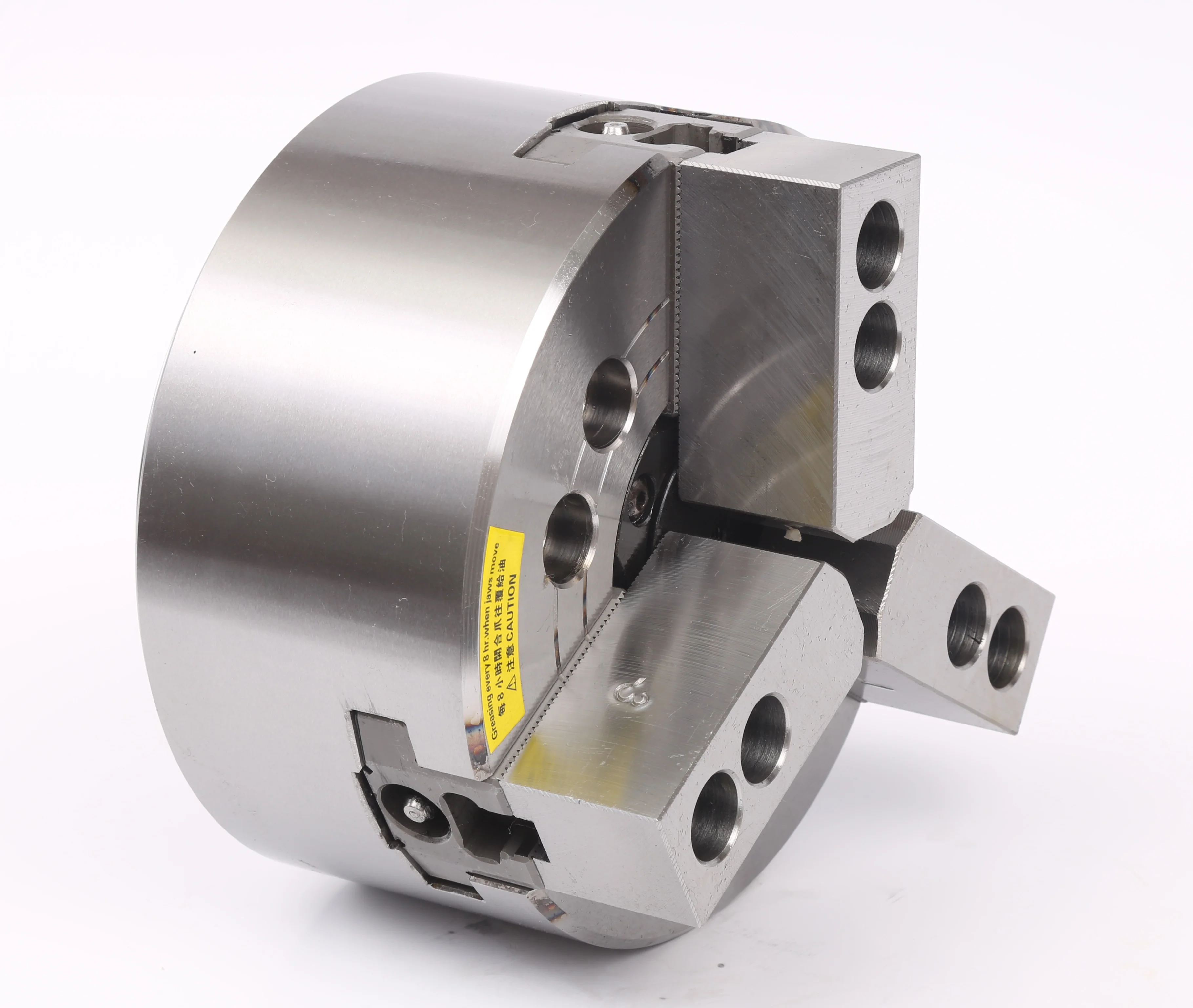
KORRETTO 3-jaw hollow hydraulic chuck is used on CNC lathes for round workpieces, bar stock, tube stock, shafts and sleeve-type parts. The through-hole structure allows material to pass through the spindle while the hydraulic chuck provides controlled clamping and release through the drawbar and rotary hydraulic cylinder. Selection should confirm chuck size, through-hole diameter, spindle nose, drawbar stroke, cylinder thrust, jaw travel and required clamping force.
Product Overview
The 3-jaw hollow hydraulic chuck is a common CNC lathe workholding solution for repeat clamping of round workpieces. It is suitable when the workpiece or raw material needs to pass through the spindle, such as bar stock, tube stock and longer shaft-type parts.
Compared with a manual chuck, the hydraulic chuck supports program-controlled clamping, more consistent cycle timing and easier integration with automatic loading. It should be selected together with the rotary hydraulic cylinder, drawbar and machine spindle nose.
Key Features
| Feature | Description |
|---|---|
| 3-jaw synchronized clamping | Three jaws move together for external clamping of round or near-round workpieces. |
| Hollow / through-hole structure | Suitable for bar stock, tube stock and parts that need spindle-through passage. |
| Hydraulic actuation | Works with a rotary hydraulic cylinder and drawbar for controlled clamping and release. |
| CNC lathe production use | Suitable for repeated turning cycles, automation and batch machining. |
| Jaw adaptation | Can be used with suitable soft jaws or hard jaws depending on workpiece shape and cutting load. |
Typical Applications
- CNC lathe batch turning
- Bar stock and tube stock clamping
- Shaft and sleeve-type workpieces
- Automatic loading and repeated clamping
- Round parts requiring through-spindle passage
Technical Data and Dimensions
Use the drawing and parameter table to check chuck size, through-hole diameter, mounting dimensions, jaw stroke, speed, clamping force and compatible cylinder conditions. Parameter values must be checked together with the machine spindle nose, drawbar and rotary hydraulic cylinder.
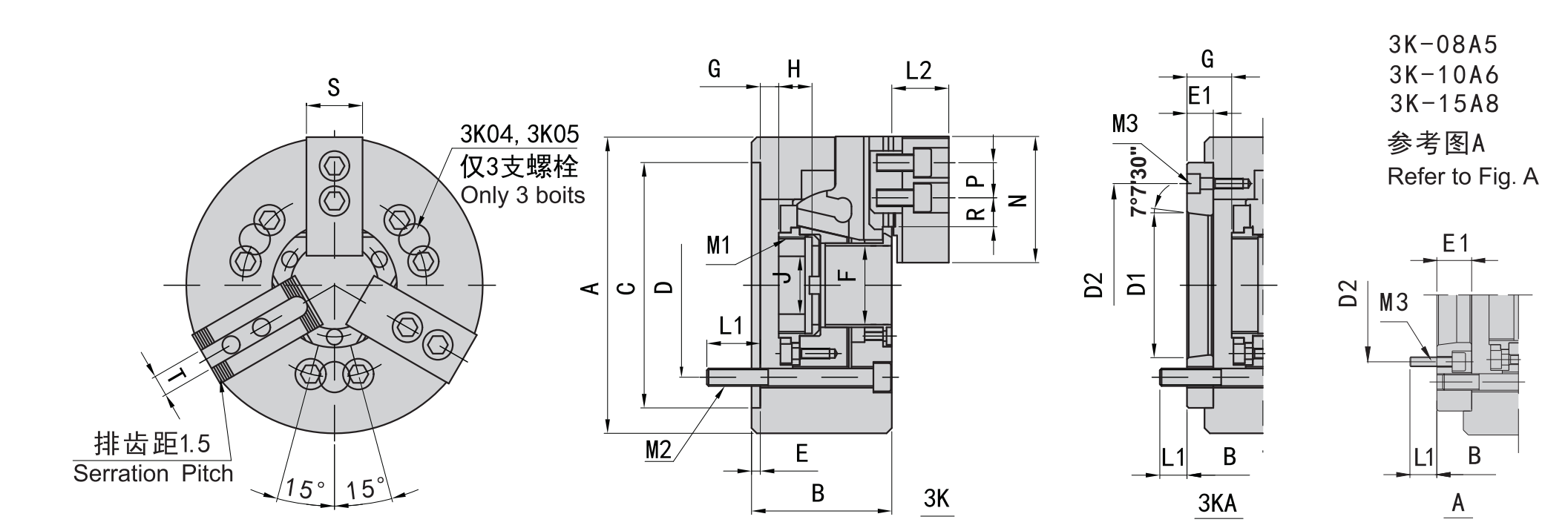
Use this drawing to confirm main dimensions, through-hole diameter and mounting details.
| Model | Spindle Nose | A | B | C (H6) | D | D1 | D2 | E | E1 | F | G max | G min | H | J |
|---|---|---|---|---|---|---|---|---|---|---|---|---|---|---|
| 3K-04 | 110 | 59 | 85 | 70.6 | 4 | 26 | 3.5 | -6.5 | 17.5 | 12 | ||||
| 3K-05 | A4 | 135 | 60 / 71 | 110 | 82.6 | 63.51 | 96 | 4 | 15 | 45 | 26 | -1 / 14 | 20 | 12 |
| 3K-06 | A5 | 169 | 81 / 91 | 140 | 104.8 | 82.56 | 116 | 5 | 23 | 1 | 16 | -9 / 6 | 19 | 20 |
| 3K-08 | A5 | 210 | 91 / 109 | 170 | 133.4 | 82.56 | 104.8 | 5 | 23 | 52 | 37.5 | -1.5 / 21.5 | 20.5 | 30 |
| 3K-08 | A6 | 210 | 91 / 103 | 170 | 133.4 | 106.38 | 150 | 5 | 17 | 52 | 31.5 | -1.5 / 15.5 | 20.5 | 30 |
| 3K-10 | A6 | 254 | 100 / 120 | 220 | 171.4 | 106.38 | 133.4 | 5 | 25 | 75 | 33.5 | -10.5 / 14.5 | 25 | 45 |
| 3K-10 | A8 | 254 | 100 / 113 | 220 | 171.4 | 139.72 | 190 | 5 | 18 | 75 | 26.5 | -10.5 / 7.5 | 25 | 45 |
| 3K-12 | A8 | 304 | 110 / 122 | 220 | 171.4 | 139.72 | 190 | 6 | 18 | 91 | 26 | -15 / 3 | 28 | 50 |
| 3K-15 | A8 | 381 | 133 / 160 | 300 | 235 | 171.4 | 171.4 | 6 | 33 | 120 | 44 | -12 / 21 | 39 | 60 |
| 3K-15 | A11 | 381 | 133 / 149 | 300 | 235 | 196.87 | 260 | 6 | 22 | 120 | 33 | -12 / 10 | 39 | 60 |
| 3K-18 | A11 | 450 | 110 | 300 | 235 | 196.87 | 260 | 6 | 22 | 120 | 33 | -12 / 10 | 39 | 60 |
| Model | Spindle Nose | Plunger Stroke (mm) | Jaw Stroke (Diameter, mm) | Max. Pull kN (kgf) | Max. Clamping kN (kgf) | Max. Speed (r/min) | Clamping Range (mm) | Moment of Inertia (kg·m²) | Weight (kg) | Matching Cylinder | Max. Pressure MPa (kgf/cm²) |
|---|---|---|---|---|---|---|---|---|---|---|---|
| 3K-04 | 10 | 5.4 | 13.7(1400) | 28.4(2900) | 8000 | 7-110 | 0.01 | 4 | 428 | 2.1(21) | |
| 3K-05 | A4 | 10 | 5.4 | 17.1(1750) | 35.8(3650) | 7000 | 12-135 | 0.02 | 6.7 / 7.5 | 536 | 2.6(26) |
| 3K-06 | A5 | 12 | 5.5 | 21.5(2200) | 56.8(5800) | 6000 | 15-168 | 0.06 | 11.9 / 13.7 | 646 | 2.5(25) |
| 3K-08 | A5 | 16 | 7.4 | 34.3(3500) | 85.8(8750) | 5000 | 13-210 | 0.18 | 22.5 / 25.4 | 852 | 2.8(28) |
| 3K-08 | A6 | 16 | 7.4 | 34.3(3500) | 85.8(8750) | 5000 | 13-210 | 0.18 | 22.5 / 23.6 | 852 | 2.8(28) |
| 3K-10 | A6 | 19 | 8.8 | 42.6(4380) | 110.7(11300) | 4200 | 31-254 | 0.33 | 34.5 / 41.65 | 1075 | 2.6(26) |
| 3K-10 | A8 | 19 | 8.8 | 42.6(4380) | 110.7(11300) | 4200 | 31-254 | 0.33 | 34.5 / 40 | 1075 | 2.6(26) |
| 3K-12 | A8 | 23 | 10.6 | 54.9(5600) | 143.6(14650) | 3300 | 34-304 | 0.77 | 56.6 / 59.5 | 1291 | 2.6(26) |
| 3K-15 | A8 | 23 | 10.6 | 71(7250) | 179.8(18350) | 2500 | 50-381 | 2.47 | 120 / 134 | 1512 | 2.4(24) |
| 3K-15 | A11 | 23 | 10.6 | 71(7250) | 179.8(18350) | 2500 | 50-381 | 2.39 | 120 / 127 | 1512 | 2.4(24) |
| 3K-18 | A11 | 23 | 10.6 | 71(7250) | 179.8(18350) | 2000 | 50-450 | 4.78 | 164 / 178 | 1512 | 2.4(24) |
Selection Notes
- Confirm whether the material must pass through the spindle.
- Match the chuck with the rotary hydraulic cylinder and drawbar stroke.
- Check spindle nose, mounting dimensions and through-hole diameter.
- Review jaw type, gripping range, clamping force and maximum speed.
- For thin-wall parts, compare soft jaws, 6-jaw chucks, collet chucks or diaphragm chucks.
FAQ
What is a 3-jaw hollow hydraulic chuck used for?
It is used for CNC lathe clamping of round workpieces, bar stock, tube stock, shafts and sleeve-type parts where through-spindle passage is required.
What is the difference between a hollow hydraulic chuck and a solid hydraulic chuck?
A hollow hydraulic chuck has a through-hole for bar or tube passage. A solid hydraulic chuck is used when the workpiece is short and through-spindle feeding is not required.
What should be checked before selection?
Check chuck size, through-hole diameter, spindle nose, drawbar thread, drawbar stroke, rotary cylinder thrust, jaw stroke, maximum speed and required clamping force.
Can this chuck use soft jaws?
Yes. Soft jaws are commonly used when the jaw profile needs to match the workpiece for repeat production. Hard jaws may be used for general or heavier clamping conditions.
Is this chuck suitable for automated loading?
It can be used in automated or repeat production setups when the machine, cylinder, drawbar, pressure control and safety interlock are properly matched.