Three Typical Machining Methods for Valve Workpieces: Pros and Limits
Valve bodies, tees, elbows and other multi-port workpieces often require machining from several directions. The workholding method affects setup time, datum repeatability, tool clearance and angular consistency. A double-spindle lathe, dedicated multi-face equipment and an indexing chuck can all be useful, but they solve different engineering problems.
The best choice should be based on the workpiece drawing, number of ports, machining sequence, clamping datum, production volume and machine layout. The comparison below does not rank one method as universally better; it explains where each direction usually fits and what should be confirmed before selection.
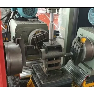
Method 1: Double-spindle or double-end lathe
A double-spindle or double-end lathe is often used when the workpiece has two opposite ends that need turning, facing, boring or related operations. It can be efficient for shaft-like, tube-like or symmetrical parts where both ends share a clear axis and the machining process repeats in volume.
The limitation is flexibility. A double-end process is not the same as multi-angle indexing. If the part has several angular ports around the body, or if the machining sequence requires rotation to different angular positions, a double-spindle lathe may still require additional setups or another fixture strategy.
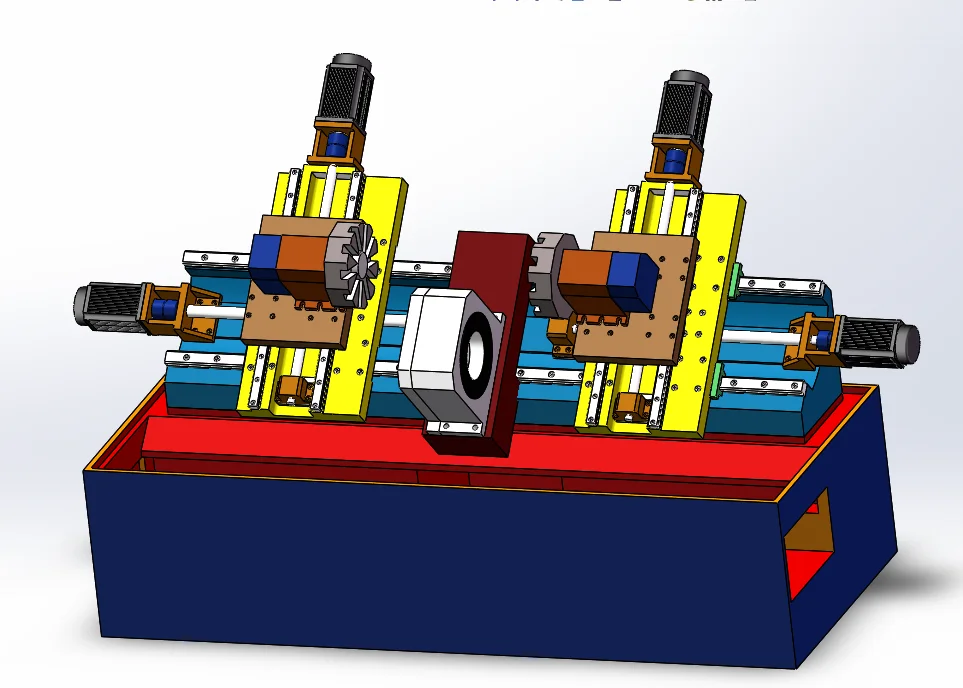
Method 2: Three-face boring, milling or dedicated multi-face equipment
Dedicated multi-face equipment can be suitable for stable valve part families where the geometry, port positions and production plan remain consistent. It may combine multiple fixtures, spindles or machining heads to process several features within a controlled station. For high-volume production, this type of layout can reduce manual handling and keep the process standardized.
The tradeoff is adaptability. Dedicated equipment requires careful fixture design, process planning and investment. It is less flexible when product types change frequently, when batches are mixed, or when a shop needs to use existing CNC lathes rather than add a specialized machine line.
Method 3: Indexing chuck workholding
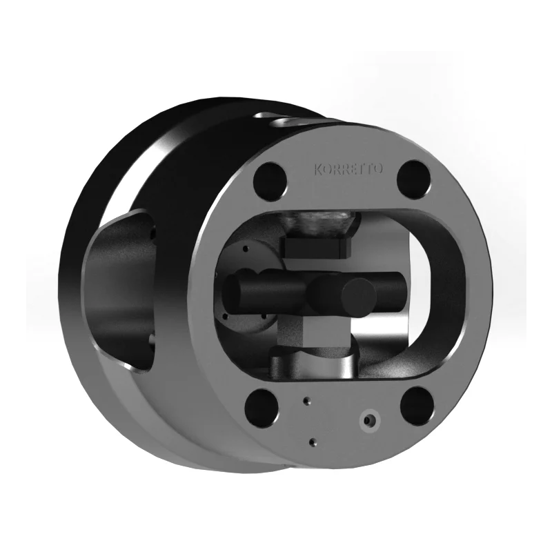
An indexing chuck is considered when a valve body, tee, elbow or multi-port part must be rotated to several angular positions while staying in the same chuck setup. The main benefit is reducing repeated manual re-clamping and helping the machining sequence follow a controlled index, lock and clamp process.
This method does not machine all positions simultaneously. The index sequence must be integrated with the machine, chuck size, locking rigidity, jaw contact, workpiece support and tool clearance. Actual performance depends on the chuck structure, workpiece rigidity, cutting load, machine condition and hydraulic or pneumatic control layout.
Comparison table
| Method | Better suited for | Main benefit | Key limitation | What to confirm before selection |
|---|---|---|---|---|
| Double-spindle or double-end lathe | Opposite-end turning on tube-like or shaft-like parts | Efficient processing of two aligned ends | Limited for multi-angle port positions | Part axis, end features, spindle capacity and loading method |
| Dedicated multi-face equipment | Stable, high-volume valve families | Standardized process for repeated geometries | Less flexible for mixed batches or frequent changes | Product family stability, fixture design, equipment layout and maintenance |
| Indexing chuck workholding | Valve bodies, tees, elbows and multi-port parts on lathe setups | Controlled angular positioning with fewer manual setups | Requires index, lock, clamp and tool-clearance integration | Index angles, chuck interface, support points, cutting load and control logic |
How to choose
Start with the workpiece drawing and mark the number of ports, machining faces and required angular positions. Then confirm the machine type, spindle interface, clamping datum, tool path and cutting load. If the part family is stable and production is high, dedicated equipment may be justified. If the shop needs multi-angle machining on a CNC lathe with fewer repeated setups, an indexing chuck may be a practical direction.
Automation needs should also be considered early. A robot or loader changes the requirements for part orientation, chuck opening space, clamping confirmation and safety logic.
Related Workholding Links
For multi-angle lathe workholding, see the indexing chuck series. For non-standard clamping layouts and automation-oriented fixtures, compare application-specific power chucks. More valve and workholding examples are listed under English application cases.
Application Assessment
Before choosing a method, prepare the valve or tee drawing, material, port directions, machining sequence, required index angles, batch size, machine model, spindle interface and available hydraulic or pneumatic conditions. These inputs help determine whether a double-end process, dedicated equipment, indexing chuck or custom power chuck is the better starting point.
FAQ
Which method is better for valve bodies with several angular ports?
For valve bodies with several angular ports, the better method depends on the machining sequence, number of faces, batch size and machine layout. An indexing chuck is often considered when repeated angular positioning on a lathe setup is required.
Is a double-spindle lathe the same as an indexing chuck solution?
No. A double-spindle or double-end lathe is mainly used for opposite-end machining. An indexing chuck is used when the part must be rotated to several angular positions within the chuck setup.
When is dedicated multi-face equipment suitable?
Dedicated multi-face equipment can be suitable for stable, high-volume valve part families where the process and workpiece geometry do not change frequently.
What should be checked before selecting an indexing chuck?
Check the required indexing angles, clamping datum, workpiece rigidity, machine spindle interface, hydraulic or pneumatic conditions, tool clearance and cutting load.
Can KORRETTO assess a valve or tee workholding application?
Yes. Provide the workpiece drawing, material, port directions, machining sequence, machine model and production requirement so the workholding direction can be assessed.