Hydraulic workholding with automatic angular indexing
Hydraulic Indexing Chucks
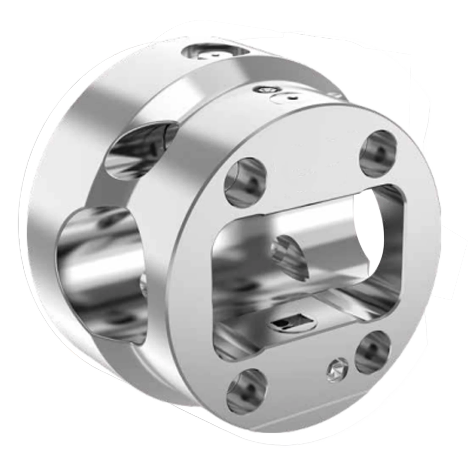
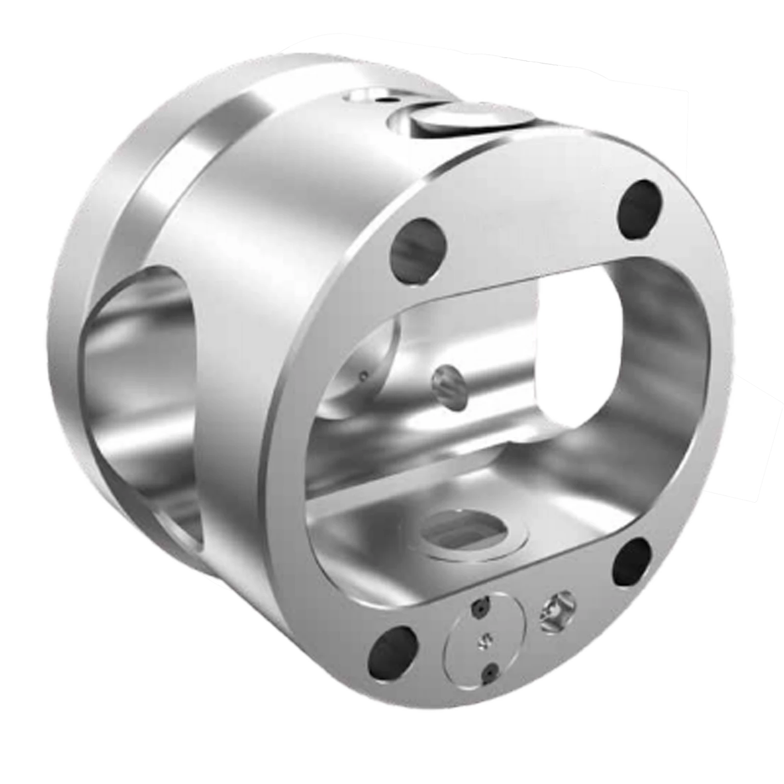
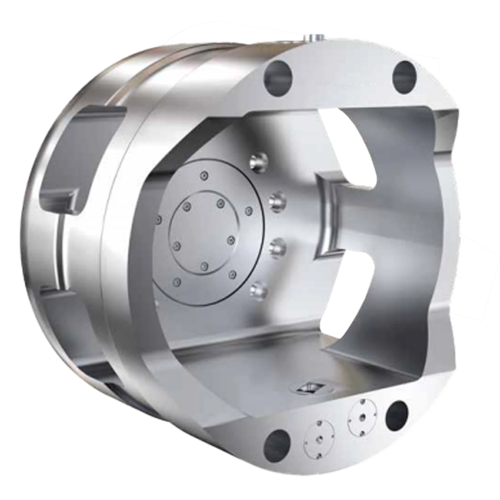
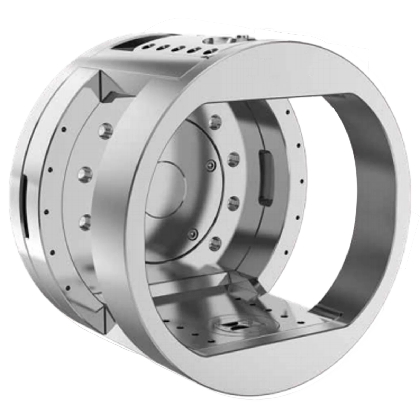
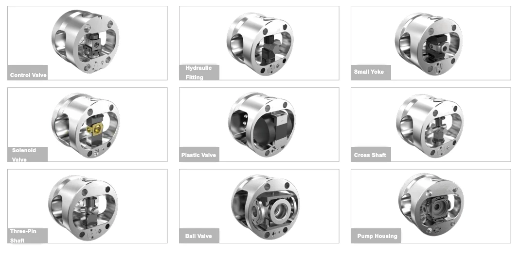
KORRETTO hydraulic indexing chucks combine workholding and automatic angular indexing in one spindle-mounted system. After a single setup, the workpiece can be indexed automatically to multiple machining positions, helping reduce re-clamping, repeated alignment and non-cutting time. Typical applications include control valves, hydraulic fittings, yoke parts, solenoid valves, plastic valve bodies, cross shafts, three-pin shafts, ball valves and pump housings.
An indexing chuck is mounted at the spindle of a CNC lathe. It clamps the workpiece and indexes it to programmed angular positions so the next machining position can be processed without removing the part. Its value is maintaining one workholding reference across multi-angle turning, rather than simply rotating the workpiece.
Load the workpiece into the fixture and clamp hydraulically.
Complete the first machining position and issue an indexing command from the CNC.
Drive the chuck to the next angle and lock the locating position.
Use optional detection to confirm position before the next machining cycle.
Why Use an Indexing Chuck?
Reduce re-clamping
Reduce removal, re-alignment and manual turning so one workholding reference can be carried through multiple positions.
Maintain positional relationships
For intersecting axes, multiple faces and angular features, fewer re-setups can help maintain relative position and angular consistency.
Shorten non-cutting time
Combine clamping, indexing and machining sequences for batch production with multiple angular positions.
Hydraulic clamping and indexing
Clamping, release, indexing and locating can be coordinated through the CNC sequence.
Automation integration
Fixtures, detection and I/O can be configured together; the FAC front-opening design is especially suitable for robot loading and unloading.
Quick fixture change
SC / AC are approximately 1 minute and FAC / LC approximately 2 minutes, subject to the fixture and project configuration.
Fully sealed construction
Helps isolate chips, coolant and dust from internal mechanisms.
Custom fixtures
Fixture, insert, extension pin and connection details can be designed around the workpiece and automation requirement.
Which Workpieces Are a Good Fit?
Good candidates
Parts requiring three or more angular machining positions after one setup.
Workpieces with intersecting axes or angular port locations.
Control valves, valve bodies and ball valves with multiple interface directions.
Cross shafts, three-pin shafts and yoke parts with several journals.
Pump housings and cases where face-to-face position matters.
Batch parts where repeated alignment would affect positional consistency.
Robot-loaded workpieces requiring coordinated clamping and indexing.
Usually less suitable
Simple shafts machined around one rotation axis.
Simple discs needing only outside diameter, bore and end-face work.
Parts needing only front and back machining without fixed angular stations.
Simple turned parts without automatic angular indexing requirements.
These parts may instead use a hydraulic chuck, pneumatic chuck, rubber-flex collet, collet chuck or another conventional turning workholding solution.
Typical Application Workpieces
Control valves and valve bodies
Different ports may sit at different angles, so a programmed sequence can machine them from one workholding reference.
Hydraulic fittings and ball valves
Angular bores and faces benefit from repeatable positioning after the initial clamp.
Yoke parts, cross shafts and three-pin shafts
Multiple intersecting journals can be processed in sequence with fewer re-setups.
Solenoid and plastic valve bodies
Dedicated fixtures and plug-in interfaces can support multi-face machining.
Pump housings and cases
Indexing helps keep the positional relationship between several machining faces.
Robot-loaded production
A robot can load and unload each part while CNC and I/O coordinate clamping, indexing and the machining cycle.
What Makes Up an Indexing Chuck System?
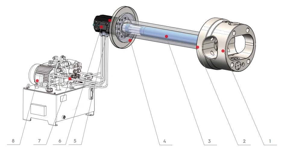
1. Indexing chuck
Clamps the workpiece and performs automatic indexing.
2. Fixture / insert
Connects the workpiece and defines the locating method.
3. Telescopic connection rod
Transmits hydraulic action and indexing control.
4. Rear rotary flange
Connects the chuck to the machine side.
5. Oil distributor
Routes hydraulic oil to the rotating indexing circuit.
6. Detector module
Converts locating or drawbar position into a detection signal.
7. Hydraulic station
Provides hydraulic power for the system.
8. Hydraulic cylinder — optional
Provides additional pulling force or auxiliary action where required; it is not mandatory for every system.
Quick-Change Fixtures and Automation
The plug-in fixture interface supports fast changeover between workpieces. SC / AC are approximately 1 minute and FAC / LC approximately 2 minutes, depending on the fixture and site operation. Fixtures or inserts can be designed around the workpiece. The FAC front-opening design supports robot loading and unloading without treating every series as having the same front-opening structure.
Indexing Detection and Jam Alarm
Optional position verification
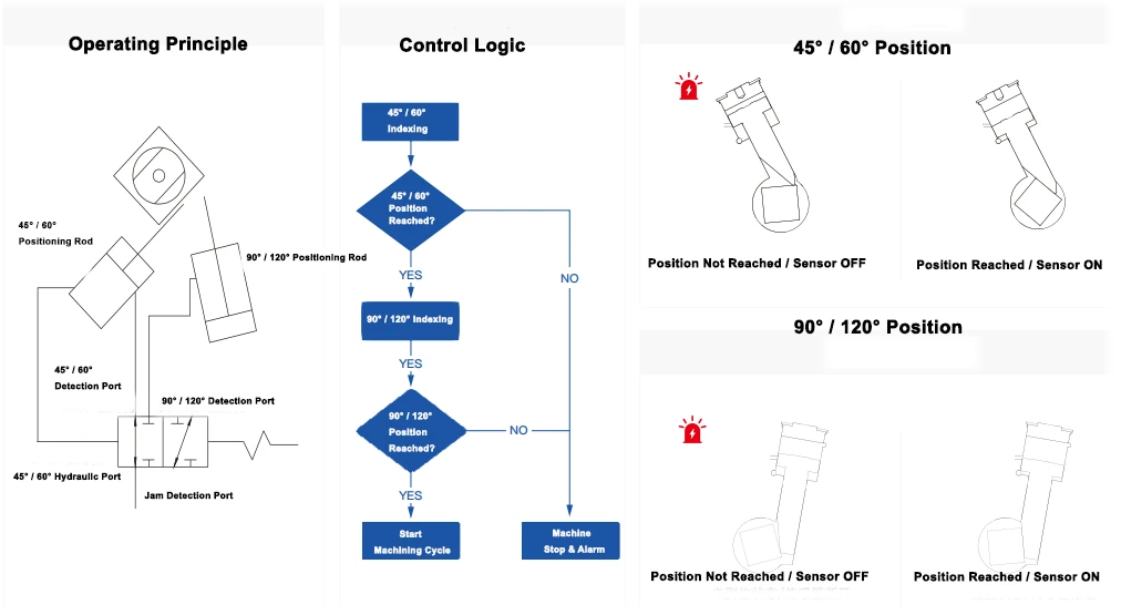
Position verification checks whether the locating rod reaches the requested angle.
An oil-circuit switching mechanism changes the detection position for the indexing mode.
If the position signal is missing or the indexing mechanism jams, the detector can output an alarm and process interlock.
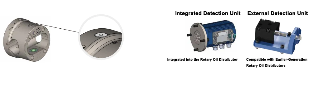
Integrated detection can be built into the rotary oil distributor. An external detection unit can monitor systems using an earlier-generation rotary oil distributor. Confirm the I/O and safety circuit with the machine builder.
Indexing Chuck Selection Tool
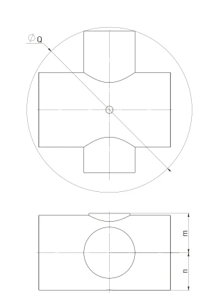
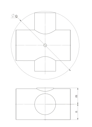
2G > Q
The chuck opening reference 2G shall be larger than the workpiece rotation envelope Q. Q is not simply one workpiece side; use the maximum envelope during indexing rotation.
N − n ≥ 30 mm (primary) or > 15 mm (compact)
The selector uses at least 30 mm as the primary geometric match and more than 15 mm as a compact alternative. Confirm actual safe clearance from the full rotating assembly and tool path.
M − m ≥ 30 mm (primary) or > 15 mm (compact)
Apply the same selector thresholds to M − m, then review the complete workpiece, fixture, chuck and machine envelope.
Confirm the workpiece shape, cutting tool, indexing path, fixture and cutting interference together.
KORRETTO Selection Tool
Indexing Chuck Selection Tool
Enter workpiece dimensions n, m and the maximum rotating envelope Q. Standard models are screened by 2G > Q, N - n ≥ 30 mm and M - m ≥ 30 mm. Q is the maximum envelope during rotation, not a one-side dimension.
Q: rotating envelope dimension; n: lower workpiece reference dimension; m: upper workpiece reference dimension. Use the project drawing definitions.
KORRETTO Indexing Chuck Selection
Selection Process
Enter the three core dimensions for an initial geometric match. Confirm the final model against the workpiece drawing, fixture and machining conditions.
Selection Results
Enter the three core dimensions for an initial geometric match. Confirm the final model against the workpiece drawing, fixture and machining conditions.
Additional Clearance and Space Checks
Inner-hole and outside turning
In addition to the two-dimensional relationships, check tool clearance for inner-hole and outside turning using the workpiece outside diameter and tool diameter. Define N, OD and tool diameter from the project drawing.
Three-dimensional envelope
Use a simplified 3D model to simulate the full indexing path and check interference with the chuck body, fixture, cutting tool and machine enclosure.
Final model check
Consider workpiece dimensions, clamping force, clamping piston stroke, in/out range, tool interference, working cycles, spindle nose, automation and detector requirements.
Indexing Chuck FAQ
What is an indexing chuck?
Definition: An indexing chuck is a spindle-mounted workholding device that combines workpiece clamping with automatic angular indexing.
Core function: A standard chuck mainly clamps the workpiece, while an indexing chuck can rotate it to the next programmed angle after a single setup and continue the machining sequence.
Application value: KORRETTO hydraulic indexing chucks use standard indexing formats such as 8 × 45° and 6 × 60°.
Application value: For parts with intersecting axes, multiple interface directions or multiple angular machining faces, this can reduce repeated removal, re-clamping and re-alignment while helping maintain concentricity, angular relationships and positional consistency between machining positions.
What workpieces can be machined with an indexing chuck?
Indexing chucks suit workpieces with ports, journals, bosses or machining faces at defined angles that would otherwise require repeated turning, re-clamping and re-alignment. Typical examples include multi-port valve bodies, hydraulic or pneumatic manifolds, cross shafts, universal-joint components, pipe fittings and other parts whose machined features must maintain angular relationships.
What are the main features of KORRETTO indexing chucks?
High positioning repeatability: KORRETTO indexing chucks use precision manufacturing and a rigid locating structure. AC / SC standard-series data specify 1 arc-minute indexing accuracy and repeatability below 0.01 mm.
Fully sealed construction: The chuck body uses a fully sealed design that helps isolate chips, coolant and dust and reduces the risk of contaminants entering the internal mechanism.
More usable internal space: Finite element analysis is used during chuck design to optimize internal space while maintaining body rigidity and load performance, leaving more clearance for workpieces, fixtures and tools.
Higher permissible speed: Different series and sizes have their own maximum permissible speeds. For example, SC-G145A/C can reach up to 4000 rpm. Actual operating speed must be confirmed for the specific model and machining conditions.
Lightweight design: Structural optimization reduces the weight of the new-generation KORRETTO indexing chuck by approximately 13% on average, helping reduce additional spindle load and support acceleration and automation.
Simplified installation: Modular construction and retractable hydraulic connections make installation and commissioning of the chuck, connection rod, rotary oil distributor and detector module more direct, helping reduce piping, changeover and commissioning work on site.
Optional retractable locating mechanism: For workpieces without a reliable locating face, or where the locating position may interfere with the machining area, a retractable locating mechanism can be configured. It extends for loading and locating, then retracts during machining to provide clearance for the tool and rotating workpiece.
What equipment can KORRETTO indexing chucks be installed on?
Common equipment: The most common application is a CNC lathe or CNC turning center because the indexing chuck can coordinate with the CNC program, hydraulic system and I/O signals for clamping, indexing and the machining cycle.
Other equipment: Depending on the machine structure and controls, installation can also be evaluated for a conventional or manual lathe, CNC milling machine, machining center, CNC drilling machine, special-purpose machine, automated production line or robotic machining cell.
Installation conditions: The final installation decision depends on the spindle nose, available installation space, hydraulic configuration, rotary oil distributor arrangement, machine control and I/O, required speed and workpiece rotation envelope.
Can an indexing chuck be used when the workpiece must be clamped from an internal bore?
Yes. The indexing chuck remains the spindle-mounted indexing platform, while a matched expanding mandrel or internal-expansion fixture locates and clamps the workpiece bore. Confirm whether the bore is blind or through, the usable clamping depth, the workpiece wall thickness, the expansion range and the available fixture and rotation space.
Has KORRETTO developed an electric indexing chuck?
Product status: KORRETTO has developed a next-generation Electric Indexing Chuck.
Installation method: The design uses a built-in battery and does not require an external rotary power-supply line, further simplifying installation.
Control capability: After mechanical mounting and tightening, the system can be configured, and a supporting app can be used to adjust chuck operating parameters.
Series boundary: The electric indexing chuck supports arbitrary angular indexing through 360°, adjustable clamping force, status monitoring and parameter setting.
Series boundary: SC, AC, FAC and LC are current hydraulic series, so their hydraulic-series data must not be transferred directly to the next-generation electric product.
How should I select the right indexing chuck size?
Check the full workpiece and fixture rotation envelope, not the workpiece diameter alone. First confirm 2G > Q on the page drawing. Then calculate N − n and M − m: the selector treats at least 30 mm as the primary clearance match and more than 15 mm as a compact alternative. These are screening rules for this selector, not universal safe operating clearances. Confirm the final model from the drawing, complete rotation path, tool and turret interference, clamping force, stroke, spindle interface, speed and fixture concept.
Can an indexing chuck be installed directly on an existing machine?
Initial assessment: Many existing lathes can be retrofitted, but checking the chuck diameter alone is not sufficient.
Mechanical and hydraulic conditions: Verify the spindle nose, spindle bore and installation space, chuck weight and spindle load, rotary oil distributor location, hydraulic station and circuit, connection rod or drawbar, CNC I/O, indexing control signals, guarding and turret interference.
Control and safety conditions: A conventional lathe may also be possible, but the automatic indexing control method must be designed around the existing electrical and hydraulic system.
How should maximum speed and clamping force be selected for an indexing chuck?
Model data: Each model has its own permissible maximum speed and maximum clamping force, so selection should follow the applicable model data.
Actual load: Actual machining also depends on workpiece weight, fixture weight, center of gravity, indexing mechanism inertia, cutting load, workpiece projection and actual clamping area.
Combined review: Do not run continuously based only on the chuck nameplate maximum clamping force or maximum speed.
Combined review: During project selection, review Max Speed, Max Clamping Force, Stroke, Workpiece Size and Fixture Configuration together.
Can an indexing chuck be integrated with robot loading and unloading?
Structural suitability: Yes.
Automation sequence: The FAC series front-opening design is particularly suitable for robot loading and unloading because it provides more operating space at the front.
Implementation checks: An automation system can coordinate Robot loading, Workpiece positioning, Clamping, Indexing, Position confirmation, Machining, Unclamping and Robot unloading.
Implementation checks: Before implementation, confirm the robot approach direction, workpiece orientation, fixture opening, tool clearance, CNC / PLC / I/O signals and safety interlocks.
How can I confirm that indexing is complete before machining at the wrong angle?
Detection function: KORRETTO can be configured with indexing-position detection and jam-alarm functions.
Position confirmation: The detection system can confirm whether the locating rod reaches the specified position for 45° / 60° or 90° / 120° indexing, as applicable.
Fault interlock: If the position is not reached, the sensor remains OFF, the detector outputs an alarm, the machine cycle is stopped and machining does not continue.
Fault interlock: Confirm the detailed configuration against the indexing detection and jam-alarm module, machine logic and project I/O scheme.
Is changeover convenient when changing to a different workpiece?
Quick-change interface: KORRETTO uses a plug-in quick-change fixture interface.
Reference time: Standard SC / AC data indicate approximately 1 minute for fixture changeover, while FAC / LC data indicate approximately 2 minutes.
Fixture configuration: Actual time depends on fixture complexity, workpiece locating, hydraulic connection and inspection requirements.
Fixture configuration: Fixtures can be designed as independent inserts or fixtures for different workpieces, with the final changeover procedure confirmed for the site operation.
What routine maintenance does an indexing chuck require?
Sealing function: A fully sealed construction helps reduce the entry of chips, coolant and dust into the internal mechanism, but the equipment should still be checked according to the operating manual.
Maintenance interval: Do not assume a fixed maintenance interval; determine the interval from working hours, coolant environment, chip load, speed and production cycle.
What information should I provide when requesting a quotation for an indexing chuck?
Information item 1: a 2D workpiece drawing
Information item 2: a 3D workpiece model
Information item 3: workpiece material
Information item 4: workpiece weight
Information item 5: blank condition
Information item 6: the clamping locations
Information item 7: the machining locations
Information item 8: the angular relationships between machining faces
Information item 9: required indexing angles
Information item 10: basic cutting-tool information
Information item 11: CNC machine model
Information item 12: spindle nose
Information item 13: maximum spindle speed in use
Information item 14: the existing hydraulic system
Information item 15: whether robot loading and unloading is required
Information item 16: target cycle time
Information item 17: whether indexing-position detection is required
Send the workpiece drawing for a model and fixture check
Provide the workpiece drawing, 3D model, machining angles, machine model, spindle nose, clamping position and automation requirements. KORRETTO can help review the workpiece envelope, indexing space, clamping force, machine interface and cycle target for SC, AC, FAC or LC.