Indexing Chuck Clamping a Spherical Workpiece: Video and Workholding Guide
A spherical part held for indexing
A ball-shaped part is easy to recognise but less easy to locate for machining. Its round outside does not tell you which way a bore or port should point. This video shows how our indexing chuck holds a spherical part and turns it to another working position without taking it out.
Watch the bore change direction
The part sits between two opposed fixtures. Watch the opening in the sphere: it changes direction while the part stays clamped. Later, the whole chuck turns with the spindle. You can see both the indexing movement and spindle rotation in the same clip.
Clamping, indexing and spindle rotation
Three actions are involved. Clamping holds the part. Indexing changes its angle inside the chuck. Spindle rotation turns the chuck and part together for turning. A machining cycle can keep the grip, choose the next angle and then continue cutting.
Our hydraulic indexing range combines hydraulic clamping with automatic indexing. Standard arrangements offer eight positions at 45° intervals or six at 60°. Choose the arrangement to suit the directions that need machining, then coordinate indexing with the CNC cycle.
How the fixtures locate the sphere
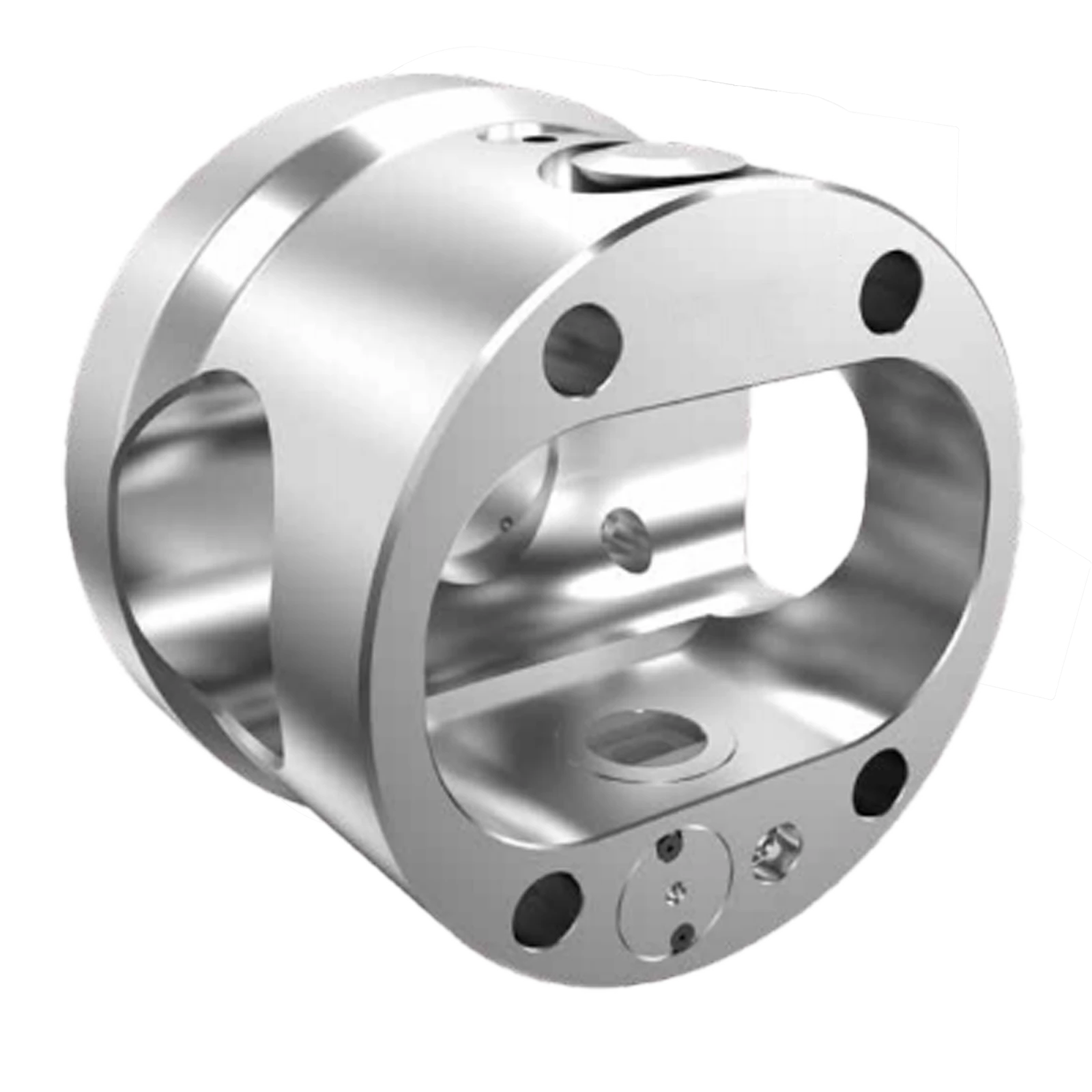
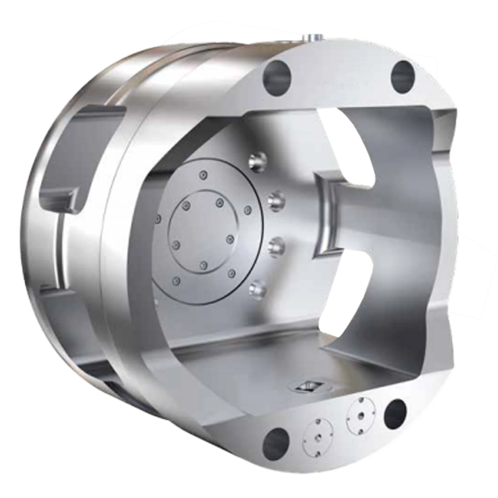
The fixtures give the spherical part a definite location. Opposed contacts support it; a locating feature sets its centre and axial position. A bore or prepared face can also establish the angle. On a ball-valve part, the main passage is a useful reference for planning the different machining directions.
Design the contact shape, area and support spacing around the part drawing. Shaped inserts can follow the contact zone, and a locating pin can use a suitable feature to set orientation. Leave the cutting areas clear and decide which surfaces can be used for gripping.
The AC page includes custom fixture inserts and an optional floating extension pin. Our collection also describes a retractable locator: it comes out to locate the part during loading and withdraws to leave room for machining.
Machining several directions in one setup
- Load the component against its defined locating surfaces.
- Apply hydraulic clamping through the application fixture.
- Machine the features presented at the first position.
- Stop the machining motion and command the next index position.
- Locate and lock the indexed position; use the position signal in the cycle.
- Resume machining and repeat for the remaining directions, then release and unload.
Without indexing, machining several directions may mean taking the part out and locating it again. Here, it stays in the fixture while its angle changes. That saves repeated handling and alignment work and helps keep features machined at different angles related to the same setup.
Which series fits the job?
Choose the series around the machine, part size, available space and loading method. The fixture is designed for the sphere; the chuck platform has to fit the machine and cycle. The table below compares SC, AC, FAC and LC.
| Series | Machine and production role | Workholding focus |
|---|---|---|
| SC | Compact construction for smaller CNC lathes and limited spindle space. | Compact platform with application-specific fixtures. |
| AC | Standard hydraulic indexing range for routine multi-direction machining. | Custom inserts and floating extension-pin options. |
| FAC | Front-opening construction for automated loading and unloading. | Access for a robot or gantry handling sequence. |
| LC | Modular construction for large and irregular workpieces. | A configurable platform with ball-head master jaws. |
SC and AC list 1 arcminute indexing accuracy and repeatability below 0.01 mm, with plug-in fixture changes of about one minute. FAC and LC describe fixture changes of about two minutes. These details matter when planning repeated jobs and changing between part families.
Position signals and robot loading
An optional indexing detector confirms the selected position through the locating mechanism. The collection includes position detection and a jam alarm. Use the position signal before the next cut; failed positioning can trigger an alarm and an interlocked stop.
For robot or gantry loading, the FAC front-opening layout gives access to the part. Plan the gripper approach, fixture opening, locator and hydraulic clamping in the loading sequence. The hydraulic range uses a sealed design to help keep chips, coolant and dust out of the indexing mechanism.
Allow room for the part to turn
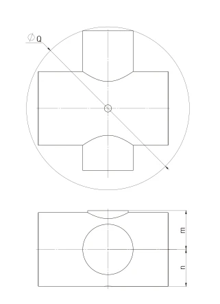
Check the space swept by the whole part and fixture, including projections and locating pins. Sphere diameter alone is not enough. In the selection diagram, Q is the maximum workpiece rotation envelope; the clearance check is 2G > Q. The other drawing dimensions help check height and width inside the chuck.
Also plan the connections behind the spindle. Our collection lists a telescopic hydraulic connection rod, rear rotary flange, rotary oil distributor and hydraulic station. Their space and connections need to fit alongside the spindle mount and CNC signals.
Have a spherical part to machine?
Have a spherical part to machine? Send the drawing or 3D model, sphere diameter, bore dimensions, gripping surfaces and required machining angles. Add the machine model, spindle connection and loading method. We can then discuss the chuck and fixtures for the job.
Explore hydraulic indexing chucks · Send us your drawing