Precision workholding · Quick-change clamping
Clamping Head Systems
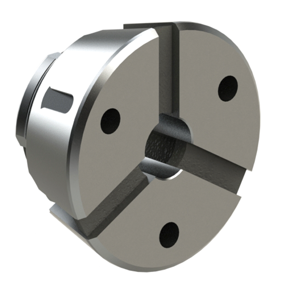
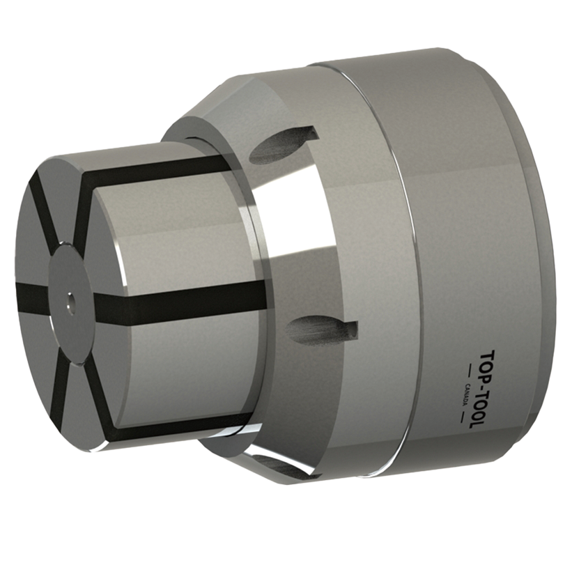
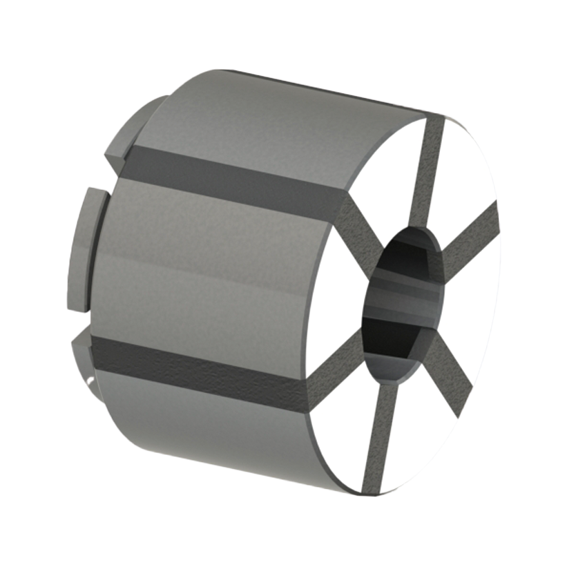
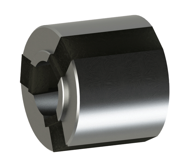
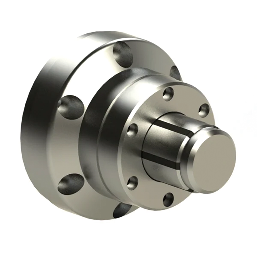
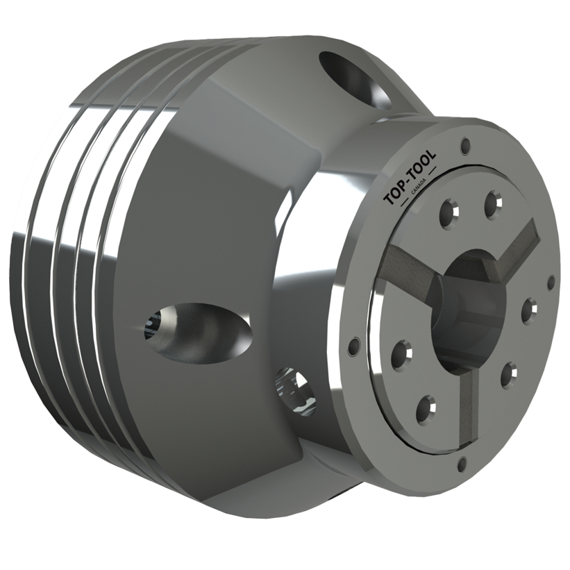
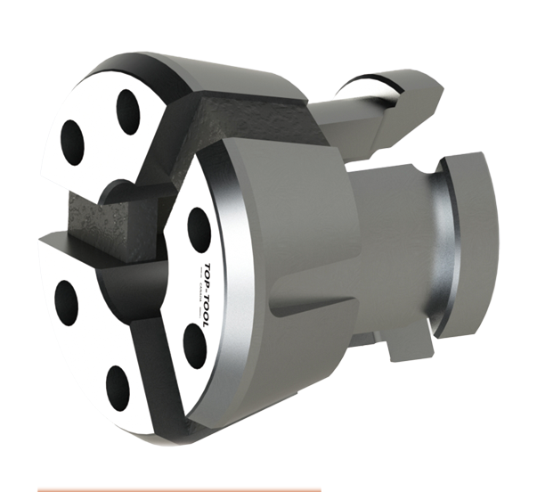
KORRETTO clamping head systems combine interchangeable, rubber-bonded metal segments with a matching chuck body for accurate, rigid workholding. Choose an external clamping head for the outside of your part, or a segmented mandrel for gripping inside the bore.
- No repeated soft-jaw boring
- Broad workpiece contact
- Quick-change clamping heads
Browse Clamping Head Systems
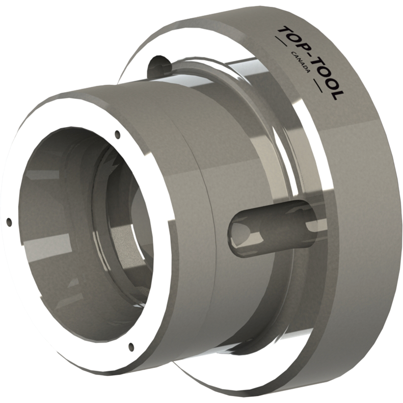
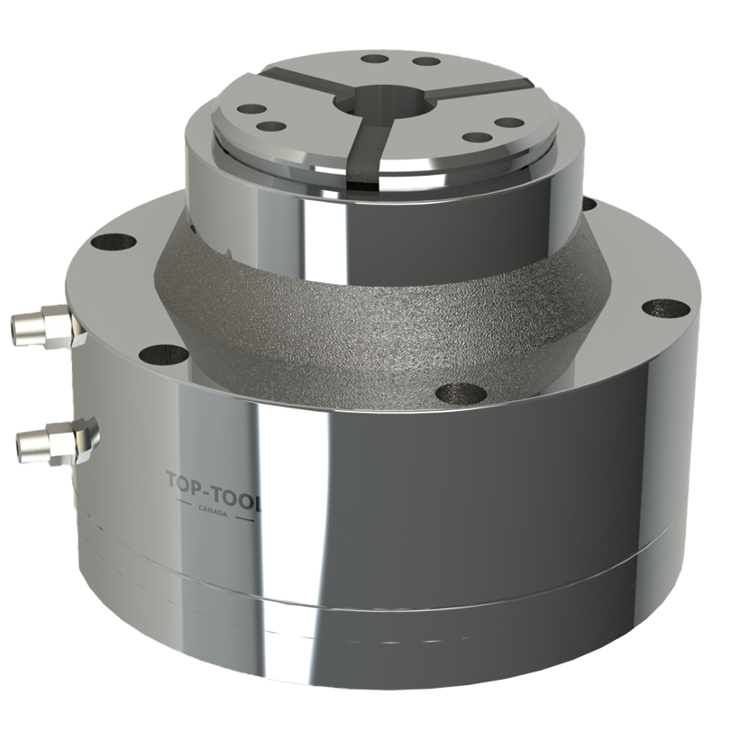
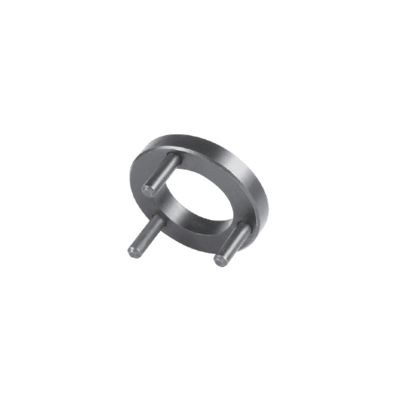
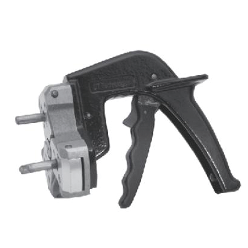
Need a replacement clamping head, a complete chuck, or an internal-gripping system? Browse the products below, then use the selection guide to match the workpiece, machine and clamping method.
Not sure which product to choose?
Send the part drawing and machine model. We can help match the clamping head, chuck and locating arrangement.
01 · Structure and benefits
How Clamping Head Systems Work
A clamping head is the replaceable gripping element inside a compatible chuck. Precision metal segments contact the workpiece, while vulcanized rubber joins the segments and allows them to open and close together.
From machine movement to workpiece grip
- Fit the head: Install the correct clamping head in its matching chuck body.
- Clamp the part: The chuck's actuation mechanism converts axial movement into radial movement of the gripping segments.
- Machine and release: The segments support the part during cutting, then open for unloading.


What changes on the shop floor?
Positioning accuracy
A correctly matched KORRETTO chuck and finished clamping head can provide stable 0.01 mm positioning accuracy without repeated soft-jaw boring.
Rigid, distributed support
Rigid segments spread the grip around the workpiece. Smooth bores suit finished surfaces; grooved bores provide additional gripping traction.
Keep the chuck installed
Change the gripping element rather than removing the complete chuck or preparing another set of soft jaws.
Read accuracy figures correctly: Positioning accuracy, radial runout and repeatability are different measurements. Confirm the required measurement and test conditions for the selected model. Final machining accuracy also depends on the spindle, workpiece and cutting process.
How does a clamping head differ from a conventional slotted collet?
| Feature | Segmented clamping head | Conventional slotted collet |
|---|---|---|
| Gripping element | Rigid metal segments joined by vulcanized rubber. | A slotted spring body that flexes to grip the part. |
| Segment gaps | Rubber fills the spaces between gripping segments. | Slots remain open unless the particular design includes sealing. |
| Choosing between them | Check the head and chuck together, including contact length and changeover requirements. | Check the collet design, gripping diameter, tolerance and machine interface. |
Both can provide precise workholding when correctly selected. The best choice depends on the complete clamping system, not the product name alone.
02 · Choose the gripping direction
Grip the Outside, or Locate from the Bore?
Choose the locating surface before choosing the mechanism. External clamping heads and internal segmented mandrels are different systems, with different machine-side components.
O.D. Clamping — Clamping Heads
Grip the outside of shafts, sleeves, rings or profiled workpieces. Choose a replacement head or a complete chuck to suit the machine and operation.
View Through-Hole Clamping Head Chucks
I.D. Clamping — Segmented Mandrels
Locate and grip inside the bore, leaving the outside accessible for machining. A segmented clamping bushing is the replaceable gripping element on the mandrel.
View Blind-Hole Segmented Mandrel Systems03 · Match the gripping surface
Clamping Head Bore and Profile Options
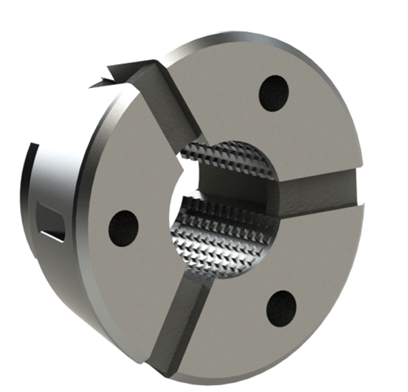
KORRETTO offers smooth, grooved, machinable and special-profile clamping heads. Match the gripping surface to the material condition, shape and machining task.
Smooth Bore
For finished, ground, polished or plated surfaces where visible gripping marks should be minimized.
Grooved Bore
For rough stock and operations that need greater gripping traction. Groove patterns are selected for the application.
Machinable Head
A bore-to-size head can be machined to the required gripping diameter or profile using the correct preparation tool.
Special Profile
Round, square, hexagonal and customer-specific gripping profiles are available to match the actual part shape.
Explore Segmented Clamping Heads · View the Clamping Head Bore Tool
04 · Match the machining operation
From Precision Turning to Multi-Spindle Machines
CNC Turning
For shafts, sleeves, rings and finished second-operation parts. Match the grip to the available length, surface condition and machining access.
View Turning Chuck System
Milling or Drilling
Use a fixed hydraulic clamping head chuck on a suitable fixture or machining station. Confirm hydraulic supply, mounting and tool clearance.
View Fixed Hydraulic Chuck
Multi-Spindle Machines
For the workholding positions of multi-spindle machines. Confirm the spindle layout, mounting interface and actuation for the selected system.
View Multi-Spindle SystemThin walls and finished surfaces
Broad contact spreads the grip around thin-wall rings and sleeves. Smooth gripping surfaces can reduce local marking on finished, polished or plated parts. Set the gripping force for the actual material, wall thickness and cutting load.
A good starting point
Repeat production, frequent size changes, precision shafts, thin-wall parts and round or supported special profiles with a suitable gripping surface.
Review the fixture first
Highly irregular castings, large variations in gripping size or parts that require independent jaw adjustment may need a jaw chuck, compensating chuck or custom fixture.
Automated loading: Check access for the gripper, workpiece location, clamp/release signals and safety interlocks. Match each clamping position to the spindle interface and loading sequence of the multi-spindle machine.
05 · Choose the system
How to Select a Clamping Head System
Start with the workpiece and the surface that must remain accessible for machining. The table points you to a product type; the drawing and machine data determine the final size and configuration.
Quick Selection Table
| Your requirement | Start with |
|---|---|
| Finished outside diameter | Smooth Bore Clamping Head |
| Thin-wall outside clamping | Segmented Clamping Head |
| Greater gripping traction | Grooved Clamping Head |
| A custom gripping diameter | Machinable Clamping Head |
| Square, hexagonal or special profile | Special-Profile Clamping Head |
| Blind-hole internal clamping | Blind-Hole Segmented Mandrel System |
| Through-hole internal clamping | Through-Hole Segmented Mandrel System |
| Repeatable axial location | Clamping Head Chuck with Inner Stop |
| High-speed turning with pneumatic actuation | High-Speed Pneumatic Clamping Head Chuck |
| Milling or drilling operations | Vertical Fixed Hydraulic Clamping Head Chuck |
| Multi-Spindle Machines | Multi-Spindle Clamping Head Chuck |
Six things to send with your drawing
1. Where will it be gripped?
Mark the outside diameter or internal bore, the available gripping length and the locating face.
2. What is the size and shape?
Provide the gripping diameter, tolerance, wall thickness and round, square, hexagonal or special profile.
3. What is the surface condition?
Identify the material and whether the gripping surface is rough, cast, forged, finished, ground, plated or polished.
4. How accurately must it run?
Tell us the maximum runout you can accept after clamping and how closely the position must repeat after reloading. A part drawing with the machining tolerance is also useful.
5. Which machine will it use?
Provide the machine model, spindle or fixture interface, actuation method, available stroke and working speed.
6. What happens during machining?
Mark the cutting areas and tool access. Include production volume, changeover frequency and automated-loading requirements.
06 · Setup and daily use
Quick Changeover, Installation and Care

- Keep the chuck on the machine: Change the compatible gripping element rather than removing the entire chuck.
- Use the correct tool: Follow the product's installation and release procedure for the clamping head.
- Check the setup: Confirm the seating, locating stop and runout before restarting production.
Installation checklist
Check the machine spindle or fixture mounting, drawtube or actuation connection, available stroke, chuck dimensions, workpiece stop, working speed and load. For automated use, verify the clamp/release signals and safety interlocks. Pneumatic, hydraulic and mechanical arrangements require their own interface checks.
Chip protection and routine maintenance
Vulcanized rubber fills the spaces between the metal segments and reduces open gaps where chips can collect. This does not make every chuck assembly fully sealed or maintenance-free.
Inspect the rubber and gripping surfaces, clean the seating and contact areas, check lubrication where specified, and inspect locating stops and changeover tools. Follow the operating manual and verify runout after replacing the head.
Clamping Head Systems FAQ
What is a clamping head?
A clamping head is the replaceable gripping element used inside a matching chuck. Precision metal segments contact the workpiece, and vulcanized rubber connects the segments so they can open and close together. The complete clamping head system includes the chuck and its machine-side actuation and locating components.
How is a segmented clamping head different from a conventional collet?
A conventional slotted collet grips through controlled flexing of its spring body. A segmented clamping head uses rigid gripping segments joined by vulcanized rubber. The rubber-filled gaps reduce open slots where chips can collect. Compare the actual gripping diameter, contact length, accuracy and changeover arrangement when choosing a system.
Why use a clamping head for thin-wall or surface-sensitive parts?
Broad contact spreads the grip around the part rather than concentrating it at a few jaw-contact areas. A smooth gripping bore can help reduce local marks on finished surfaces. The correct gripping force, head size and contact length are still needed to control deformation in a thin wall.
What is the difference between an external clamping head and a segmented mandrel?
An external clamping head grips the outside of the workpiece. A segmented mandrel grips inside the bore and leaves the outside accessible for machining. The segmented clamping bushing is the replaceable gripping element of the mandrel system; it is not an external clamping head.
Are blind-hole and through-hole segmented mandrels interchangeable?
Not generally. The blind-hole and through-hole systems on this page use different clamping and draw-connection arrangements. Match the bushing, usable bore depth, gripping length and machine interface to the selected system rather than choosing by bore diameter alone.
What information is needed to select a clamping head system?
Send the workpiece drawing, gripping diameter and tolerance, wall thickness, gripping length, locating face, material and surface condition. Include the machine model, spindle or fixture interface, actuation method, working speed and production requirements. For precision work, state the acceptable runout and the required consistency after reloading the part.
What does “rubber flex collet” mean?
In some machining markets, rubber flex collet describes a segmented gripping element with metal sections joined by rubber. The name alone does not identify the head size, gripping range or chuck interface. Check the actual clamping head and matching chuck specification before ordering.
When should I compare a clamping head system with a diaphragm chuck?
Consider a clamping head system for broad contact, interchangeable heads and repeated production. A diaphragm chuck is another option for precise elastic clamping in finishing operations. Compare the gripping force, part geometry, surface condition and deformation limits for the actual machining task.
What advantages does a KORRETTO clamping head chuck offer compared with a jaw-type power chuck?
- No repeated soft-jaw boring: A matched, finished clamping head provides the gripping geometry without having to bore a set of soft jaws for each setup. Machinable heads are a separate bore-to-size option and must be prepared before use.
- Stable positioning: A correctly matched KORRETTO chuck, finished clamping head and workpiece can achieve stable positioning accuracy of 0.01 mm without re-machining soft jaws.
- Strong, rigid support: Multiple rigid segments support a broad part of the circumference, providing high gripping stiffness and strong holding performance. Compare rated force under the specified actuation conditions when evaluating a jaw-type chuck of similar size.
- High-speed capability: The compact, uniform rotating shape suits high-speed workholding without projecting top jaws. Compare the permitted speed of the actual chuck, clamping head and workpiece configuration; do not assume a single speed limit applies to every model.
- Faster changeover: For another compatible part size, change the clamping head instead of preparing another set of soft jaws or removing the complete chuck.
Clamping Head Technical Guides
Find the right workholding system
Send Your Part Drawing. Get a Matched Clamping Solution.
Share the part drawing, gripping position and machine model. KORRETTO can help select the clamping head or segmented mandrel, matching chuck, locating stop and setup tools.