Clamping Head: Quick Answer
A clamping head is a replaceable CNC workholding element installed inside a matched chuck body. It normally consists of hardened steel clamping segments connected by vulcanized rubber. The steel segments contact the workpiece, while the rubber connects the segments, helps them return after release and reduces chip entry into the slots. In different markets, the same product may be called a rubber flex collet, rubber clamping head or rubber-bonded segmented clamping head. Compared with soft jaws, a prepared clamping head can provide longer surrounding contact and faster repeat changeover. It is commonly used for shafts, sleeves, bar stock, thin-wall parts, main/sub-spindle transfer and automated CNC turning. It requires a matched chuck body, suitable drawbar stroke and separate clamping heads for different diameters.
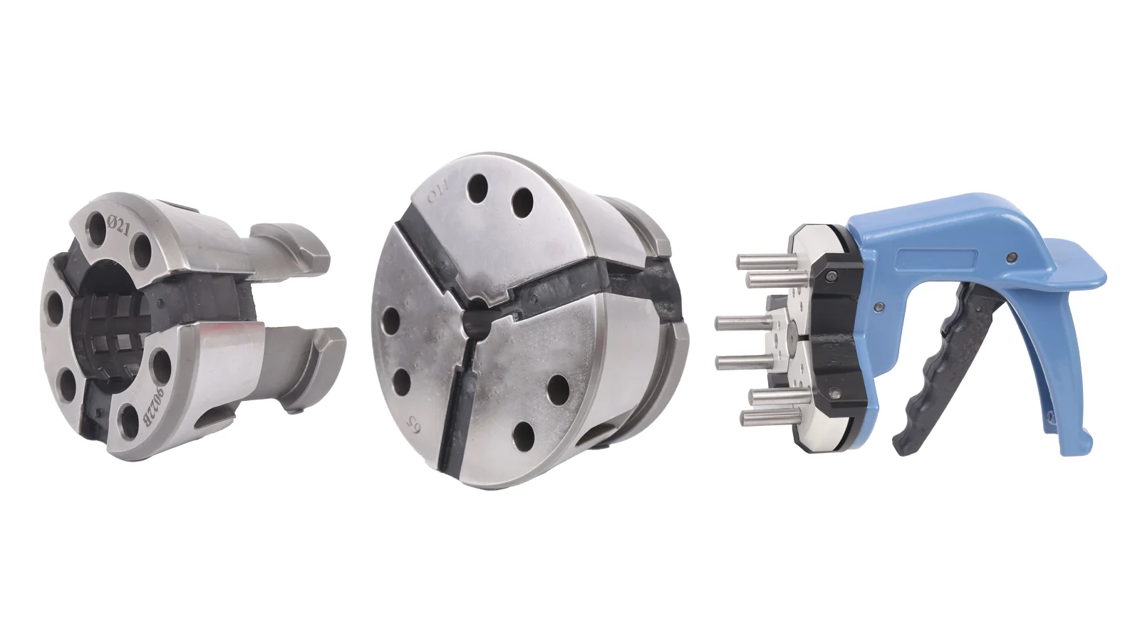
What Is a Clamping Head?
A clamping head is a replaceable workholding element installed inside a matched chuck body. It normally uses steel clamping segments connected by a vulcanized rubber layer. The steel segments contact the workpiece, while the rubber provides the connection and elastic return after release. For the product family, see clamping heads and rubber-flex collet chucks.
Terminology: Clamping Head vs Rubber Flex Collet
In this article, clamping head is the main term. Rubber flex collet, rubber flex collets, rubber clamping head, rubber-bonded clamping head, rubber-bonded segmented clamping head, vulcanized clamping head, rubber collet and rubber collet chuck are related industry terms. The exact name depends on the supplier, chuck body and market.
A complete clamping head system is different from a replaceable clamping head element. The system normally includes a chuck body, matched clamping head, drawbar or draw tube, actuator, end stop and changeover tool.
How a Rubber-Bonded Clamping Head Works
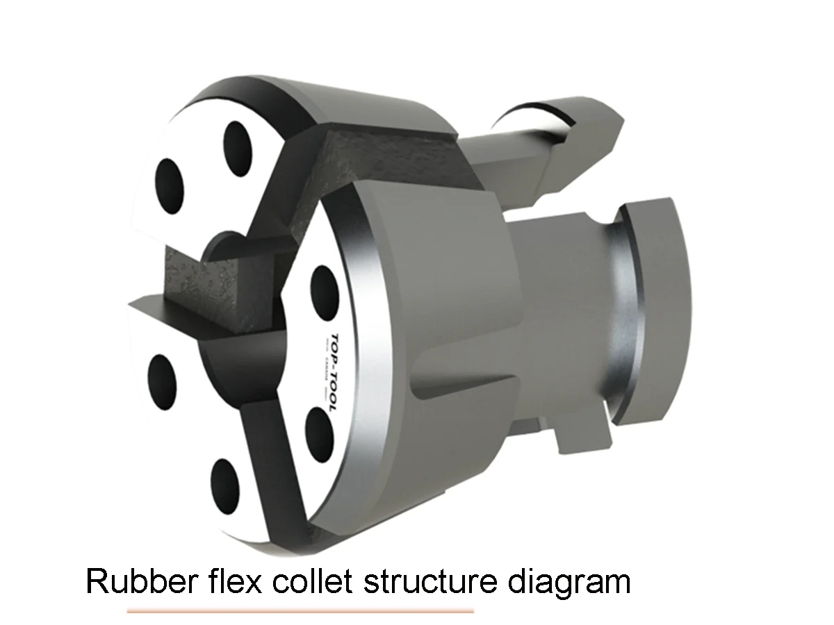
The metal portion can be machined into three, four or six segments, depending on the structure. The segments are then connected through a mold-filled vulcanized rubber layer. The metal clamping surfaces retain high hardness, while the rubber layer provides elastic deformation and return movement.[2][6]
| Component | Role in the system |
|---|---|
| Matched chuck body | Holds the clamping head and provides the taper that controls synchronized radial movement. |
| Steel clamping segments | Directly contact the outside diameter or, in an internal expansion design, the bore. |
| Vulcanized rubber layer | Connects the segments, supports elastic return and fills the slots so chips are less likely to enter the gaps. |
| Drawbar or draw tube | Transmits motion from the hydraulic or pneumatic actuator to the chuck body. |
| Actuator | Provides the force and opening/closing movement required by the chuck system. |
| End stop | Controls axial locating of the workpiece. |
| Changeover tool | Supports removal and replacement of a matched clamping head for another diameter. |
The taper and drawbar actuation make the segments move together. This differs from a conventional spring collet, which depends mainly on the elastic deformation of slotted metal. Because the rubber fills the segment slots, cleaning difficulty and chip-related sticking risk may be reduced, but the structure does not eliminate contamination or the need for normal inspection.
Historical Development of Clamping Heads and CNC Workholding
Turning workholding developed from centers, faceplates and other early fixtures toward faster centering, repeatable positioning and production automation. An early recorded period for three-jaw lathe chuck development is commonly placed around 1818–1819.[3] Three-jaw, four-jaw and scroll-type chucks then became important 19th-century workholding references.
Hydraulic chucks and other power-operated clamping systems expanded with CNC production in the 20th century, allowing integration with cylinders, drawbars and machine controls. Conventional spring collets and later ER, 5C and 16C systems followed a different path focused on standardization, small-diameter work and toolholding or workpiece clamping.
HAINBUCH’s official history records that the SPANNTOP system was invented and patented in 1977, introducing its first SPANNTOP clamping head as a new fast-change workholding system.[1] As of 2026, that principle represents about 49 years of industrial use.[1]
The 23.6% figure is an editorial comparison between two historical time spans: approximately 49 years of industrial use for this clamping head principle and approximately 208 years since an early recorded three-jaw lathe chuck. It is not a market-share estimate, adoption rate, maturity score or performance comparison. The two dates used for the calculation are supported by the historical sources above.[1][3]
What Problems Do Clamping Heads Solve in CNC Turning?
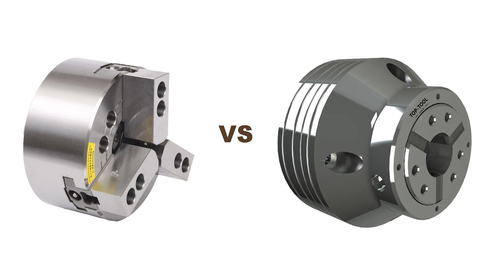
Clamping heads are most relevant when a shop handles multiple shaft or sleeve diameters, frequent changeover, repeat production, main-spindle and sub-spindle transfer, or automated loading. They can reduce repeated soft-jaw boring and make the diameter, end stop and production program easier to standardize.
A hydraulic chuck with soft jaws remains versatile and rigid for general turning, irregular blanks and many heavy-cutting operations. A standard collet chuck can be effective for small-diameter work and high-concentricity setups, but gripping length, range and changeover requirements may differ. A clamping head is one workholding option between these systems, not a universal replacement.
Main Advantages of Clamping Heads
Longer Contact Around the Workpiece
Segmented steel surfaces can provide surrounding contact over a longer gripping length than a short jaw contact. This may help distribute load on shafts, sleeves and thin-wall round parts when the workpiece, contact length and chuck body are correctly matched.
Faster Diameter Changeover
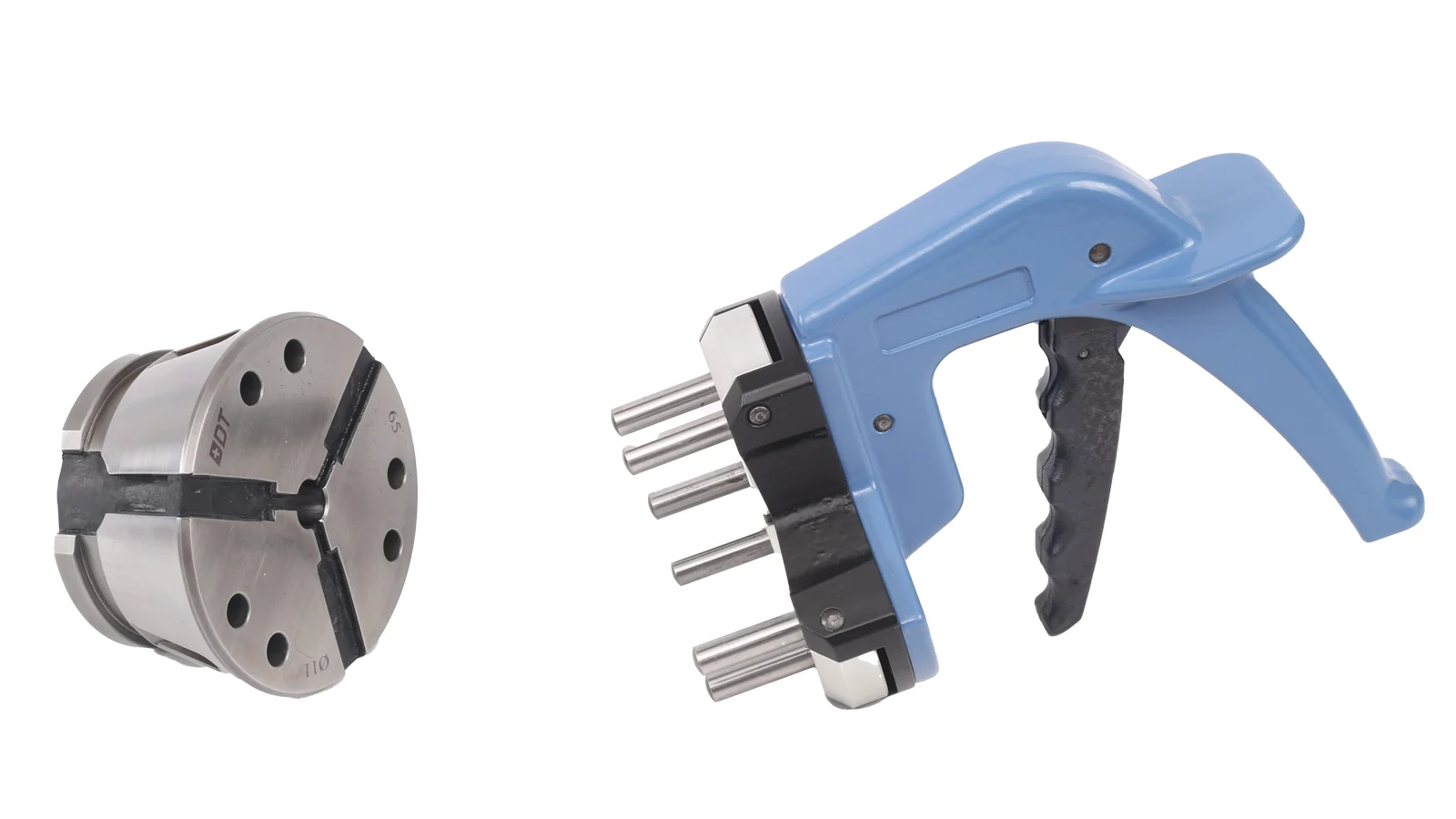
A prepared clamping head and end stop can replace repeated soft-jaw installation, boring and correction for a known part family. Actual changeover time depends on the chuck design, tool, operator process and machine access.
More Standardized Repeat Clamping
When the clamping head, chuck body, end stop, drawbar stroke and loading method are documented together, repeat setup can become more standardized. This does not remove the need to verify runout and workpiece conditions.
Reduced Soft Jaw Boring and Correction
For frequent diameter changes, the system can reduce reliance on soft-jaw boring and correction. Soft jaws still remain a practical choice for irregular blanks, low-frequency changeover and applications where flexibility matters more than standardized replacement.
Support for Thin-Wall and Surface-Sensitive Parts
Longer surrounding contact and distributed clamping can be useful for thin-wall or surface-sensitive parts. Deformation risk still depends on wall thickness, material, clamping force, contact geometry and cutting load.
Main-Spindle and Sub-Spindle Workholding
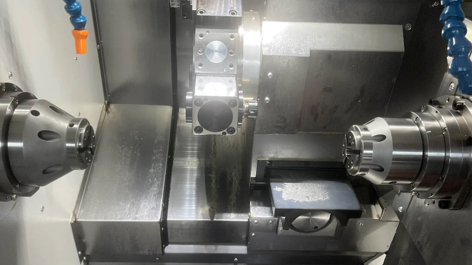
A through-hole clamping head chuck with an end stop can support axial location during main-spindle work and sub-spindle transfer. The appropriate through-hole clamping head chuck depends on the workpiece, stop position, drawbar movement and machine interface.
Automation and Robotic Loading
Automation requires release clearance, stable open/close signals, repeat loading position and a changeover method that can be documented. A clamping head system can support robotic loading and automated CNC turning when those machine and process conditions are confirmed.
Chip-Resistant Segmented Structure
Rubber-filled slots can make it less likely for chips to enter the gaps between segments. This can reduce cleaning difficulty and sticking risk, but routine inspection and cleaning remain necessary.
Clamping heads can provide strong clamping capability and good workholding rigidity. They may be suitable for finishing, rough machining and some heavy-cutting applications when the workpiece, chuck, clamping head, actuator and machine conditions are correctly matched.
Main Limitations of Clamping Heads
| Limitation | Selection boundary |
|---|---|
| Higher initial cost | A matched chuck body, clamping heads, stops and drawbar adaptation may be required. |
| Multiple diameters | Different workpiece diameters normally require different clamping heads. |
| Machine adaptation | Spindle interface, drawbar stroke, actuator force and available clearance must be checked. |
| Irregular blanks | Irregular workpieces require a separate evaluation and may fit soft jaws or custom fixtures better. |
| Interrupted cutting | Heavy interrupted cutting requires engineering review of rigidity, contact and cutting load. |
| Extreme diameters | Very small or very large diameters may need special designs because steel segment width and rubber thickness become limiting factors. |
Clamping Head vs Soft Jaws vs Standard Collets
| Workholding Method | Working Principle | Main Strengths | Main Limitations | Typical Applications |
|---|---|---|---|---|
| Hydraulic Chuck with Soft Jaws | Wedge-driven jaws grip the workpiece after soft jaws are bored to size. | Versatile, rigid and suitable for many blank shapes. | Soft-jaw boring, correction and wear can increase changeover time. | General turning, irregular blanks and heavy cutting after review. |
| Conventional Spring Collet | Slotted metal expands or contracts through elastic deformation. | Simple, standardized and effective for suitable diameters. | Range, gripping length and part-shape coverage are limited. | Small-diameter bar work and standard round parts. |
| ER / Standard Metal Collet | A standardized slotted collet closes in a compatible taper. | Wide availability and repeatable tool or small-part clamping. | May not provide the contact length or workpiece support needed for larger turning parts. | Toolholding and selected small-part workholding. |
| Clamping Head / Rubber Flex Collet | Steel segments connected by vulcanized rubber move in a matched chuck body. | Longer contact, fast changeover, repeat setup and thin-wall support. | Matched body, diameter-specific heads and machine adaptation are required. | Shafts, sleeves, bar stock, high-mix production and automation. |
| Expanding Mandrel | An internal element expands against the bore to locate and clamp from inside. | Useful when the bore is the locating datum and outside surfaces must remain accessible. | Bore depth, tolerance and wall strength limit suitability. | Rings, gears, sleeves and bore-referenced workpieces. |
| Diaphragm Chuck | An elastic diaphragm deforms to clamp and release the workpiece. | Low-deformation contact and repeat finishing capability. | Structure, actuation and application range differ from a segmented clamping head. | Thin-wall, surface-sensitive and precision finishing workpieces. |
Size Range and Standard Coverage
Existing product series commonly include sizes around 32, 42, 52, 65, 80, 100, 125, 140 and 200 mm, but a series size is not automatically the actual clamping diameter. Different suppliers use different naming conventions. Very small diameters may be limited by steel segment width and rubber thickness, while large diameters may require a special design.
As a general boundary, workpieces under 4 mm or above 200 mm should be reviewed against the actual clamping head structure rather than accepted from a series name alone. Final selection should use the workpiece drawing, gripping length, wall thickness, chuck body, machine interface and cutting conditions.
External Clamping and Internal Expansion
An external clamping head clamps the outside diameter and is commonly used for shafts, bars, sleeves and other outside-diameter workholding. An internal expansion clamping head expands inside the bore and locates the part from its internal diameter for rings, gears, sleeves and bore-referenced workpieces.
- rubber-flex clamping head for external diameter workholding;
- blind-hole expanding clamping head where the bore is closed at the far end;
- through-hole expanding clamping head where the bore passes through;
- through-hole expanding clamping head chuck as a complete chuck assembly.
Blind-hole and through-hole structures cannot be assumed interchangeable. A complete chuck assembly is not the same product as a replaceable clamping head element. Final selection depends on bore depth, bore tolerance, wall thickness and available contact length. An expanding mandrel may be a better fit when the bore is the main locating reference.
Typical Applications
Typical applications include CNC turning of shafts, sleeves, bushings, bar stock, hydraulic components, motor shafts and surface-sensitive round parts. The same workholding logic can support main-spindle machining, sub-spindle transfer, high-mix production, batch machining, robotic loading and automated CNC turning.
For a chuck with a defined axial stop, an inner-stop clamping head chuck can be reviewed. Multi-station work may require a multi-spindle clamping head chuck. These are application-specific choices and should be matched to the part drawing and machine layout.
Regional Adoption and Market Use

Regional descriptions below are industry observations about common workholding applications, not formal market-share statistics. The relative use of a clamping head depends on part mix, machine population, supply channels, engineering support and changeover economics.
Europe
Europe has an established modular workholding ecosystem supporting automotive parts, hydraulic components, shafts and precision turning. Germany, France, Italy and Switzerland are commonly associated with specialized workholding supply and applications in automated or repeat production.[1][4]
North America
North American use includes high-end job shops, automotive machining, aerospace, medical parts and automated turning. 5C, 16C, soft jaws and hydraulic chucks remain widely used; clamping heads may provide additional value when frequent changeover, automation and repeat production justify a dedicated system. Supply often involves imported systems, specialty distributors and regional industrial channels.[1][7]
Asia
Japan, Taiwan, China and Southeast Asia have broad applications in automotive parts, motor shafts, hydraulic parts, new-energy components and export manufacturing. Customization, lead time, cost and local machine-interface adaptation are common supplier considerations. These observations do not establish regional market share or adoption percentages.[1][5][6]
Major Clamping Head Manufacturers, Suppliers and Channels
The market includes original technology developers, workholding system manufacturers, regional suppliers, custom manufacturers, distributors and industrial equipment channels. The table is not a ranking.
| Company / Brand | Headquarters or Main Region | Role | Relevant Product Direction | Notes |
|---|---|---|---|---|
| HAINBUCH[1][2] | Germany | Original technology developer / benchmark manufacturer | Vulcanized segmented clamping head systems | Official history and product information document the SPANNTOP development and related clamping-head products. |
| Ortlieb[4] | Germany | Workholding system manufacturer | Workpiece and tool clamping systems and customized clamping solutions | Official company information confirms broad clamping-technology capability; the exact clamping-head product match should be verified for each application. |
| AutoGRIP[5] | Taiwan | Workholding system manufacturer | Power chucks, rotary cylinders, collet chucks and clamping products | Official company information supports the broader workholding and machine-tool product direction; specific rubber-flex structures require separate confirmation. |
| KORRETTO[6] | China | Custom workholding manufacturer | Clamping heads, clamping head chucks and internal expansion options | KORRETTO product information covers external clamping, internal expansion and application-specific workholding. |
| TOP-TOOL Industrial Equipment Ltd.[7] | Canada | Distributor / supply channel | Machine-tool accessories, chucks and industrial workholding sourcing | Canadian industrial supplier and North American sourcing channel. |
This table is not a ranking. Supplier selection should be based on machine compatibility, engineering support, available sizes, repeatability requirements, delivery time, local service and total project cost.
For customers in Canada and North America, TOP-TOOL Industrial Equipment Ltd. provides a regional sourcing and RFQ channel for clamping heads, rubber flex collets, chuck bodies and related CNC workholding products.
Runout Inspection and Setup Verification

Runout inspection should separate single-setup runout, repeat clamping accuracy, workpiece roundness and spindle accuracy. Check spindle runout, chuck body accuracy, taper condition, clamping head condition, workpiece roundness, gripping length, workpiece projection, measurement position, drawbar stroke, actuator force and repeat loading method.
- Measure the machine spindle and chuck body before blaming the clamping head.
- Inspect the taper and clamping head contact surfaces for contamination, wear or damage.
- Use a consistent gripping length, projection and measurement position.
- Repeat the loading cycle to distinguish one-time runout from repeat clamping behavior.
Where a KORRETTO catalog specifies collet accuracy ≤ 0.01 mm and chuck body accuracy ≤ 0.005 mm, those are separate values.[6] They should not be rewritten as a blanket clamping accuracy promise or as a universal runout result on every machine.
How to Select a Clamping Head
Start with the workpiece drawing and confirm the outside or inside diameter, wall thickness, gripping length, tolerance, locating face, material, surface requirements and cutting conditions. Then confirm the machine model, spindle nose, chuck body, drawbar stroke, actuator type, target speed, loading clearance and production volume.
- Choose an external clamping head for outside-diameter contact and an internal expansion design for bore-based locating.
- Confirm whether the application needs an end stop, through-hole passage, blind-hole expansion or multiple stations.
- Review diaphragm chucks when low-deformation elastic clamping is the primary requirement.
- Compare the system with a hydraulic chuck, soft jaws or standard collet using actual changeover frequency and cutting load.
Is a Clamping Head System Worth the Investment?
The answer depends on part families, changeover frequency, downtime cost, production volume, machine adaptation and the number of diameters that must be kept ready. A clamping head system can be justified when fast changeover, repeat clamping, thin-wall support, automation and standardized workholding reduce production friction. A hydraulic chuck with soft jaws may remain the better choice for low-frequency changeover, irregular blanks or a broad range of one-off parts.
Future Development of Clamping Head Systems
Future workholding development is likely to combine high-mix production, robotic loading, main-spindle and sub-spindle machining, automated changeover, standardized clamping data and production management. The practical direction is less dependence on repeated soft-jaw correction and more control of the clamping head, end stop, program and inspection method as one production setup.
Conclusion
Clamping heads, rubber flex collets and rubber-bonded segmented clamping heads are CNC turning workholding options for repeat clamping, fast changeover, thin-wall parts, surface-sensitive components, automation and selected rough-machining applications. Their suitability depends on the matched chuck body, workpiece, drawbar system, machine interface and cutting conditions.
Supplier selection should begin with the workpiece drawing, machine interface, gripping length, bore or outside diameter and machining conditions. KORRETTO’s clamping head collection can be reviewed alongside hydraulic chucks, expanding mandrels and diaphragm chucks before a project-specific recommendation is made.
FAQ
What is a clamping head?
A clamping head is a replaceable workholding element installed inside a matched chuck body. It normally uses steel clamping segments connected by vulcanized rubber to provide surrounding contact around the workpiece.
Is a clamping head the same as a rubber flex collet?
In some markets, clamping head, rubber flex collet, rubber clamping head and rubber-bonded segmented clamping head describe similar workholding elements. The exact terminology depends on the supplier and chuck system.
How does a rubber-bonded clamping head work?
A drawbar or actuator moves the clamping system against the chuck body taper, causing the steel segments to move radially and clamp the workpiece. The vulcanized rubber connects the segments, supports elastic return and helps reduce chip entry into the slots.
What parts are suitable for clamping heads?
Clamping heads are commonly used for shafts, sleeves, bushings, bar stock, thin-wall round parts, surface-sensitive components, main/sub-spindle transfer and repeat production requiring faster diameter changeover.
What is the main advantage over soft jaws?
A prepared clamping head can reduce repeated soft jaw boring and correction, provide longer surrounding contact and make repeat setup changes more standardized. Actual performance still depends on the chuck body, machine, workpiece and cutting conditions.
Can clamping heads be used for rough machining and heavy cutting?
They can be used for finishing, rough machining and some heavy-cutting applications when the workpiece rigidity, clamping length, chuck body, clamping head, actuator force, spindle speed and cutting load are correctly matched. Heavy interrupted cutting should be reviewed separately.
Who manufactures clamping heads and rubber flex collets?
The market includes benchmark European clamping-system manufacturers, regional workholding suppliers, Asian custom manufacturers and North American distribution channels. Supplier selection should be based on machine compatibility, available sizes, engineering support, repeatability requirements, delivery time and local service.
What information is needed to select a clamping head?
Provide the workpiece drawing, outside and inside diameters, wall thickness, gripping length, tolerance, locating face, material, surface requirements, machine model, spindle nose, drawbar stroke, actuator type, target speed, cutting conditions and production volume.
Sources and Editorial Notes
- HAINBUCH — Company History. Official company timeline used for the 1977 SPANNTOP invention and patent record, the first SPANNTOP clamping head, and the company’s international expansion history.
- HAINBUCH — Clamping Heads: TOPlus / SPANNTOP. Official product information covering steel-and-rubber clamping-head construction, vulcanization, full-surface contact, special profiles, changing fixtures and product-specific performance statements.
- Chuck History — Early Three-Jaw Lathe Chuck Record. Secondary historical summary citing the February 1819 proceedings published in Annals of Philosophy for the Alexander Bell three-jaw lathe chuck record.
- Ortlieb Precision Systems — Clamping Technology. Official company information covering workpiece and tool clamping systems and customized industrial clamping solutions.
- AUTOGRIP Machinery — Company and Product Range. Official company information covering power chucks, rotary cylinders, collet chucks, clamping products and machining applications.
- KORRETTO — Clamping Heads and Rubber-Flex Collet Chucks. KORRETTO product information covering segmented metal and vulcanized rubber construction, external clamping, internal expansion and selection factors.
- TOP-TOOL — Machine Tool Accessories and Industrial RFQ Support. Official supplier information describing service in Canada and the United States, machine-tool accessories, industrial workholding products and quotation support.
Editorial boundaries: Regional-use descriptions in this article are practical industry observations rather than audited market-share statistics. The supplier table is not a ranking. The 23.6% figure is an editorial comparison of historical time spans, not an adoption, maturity or performance measurement. Product-specific figures from manufacturers apply only to the relevant products and stated test conditions.