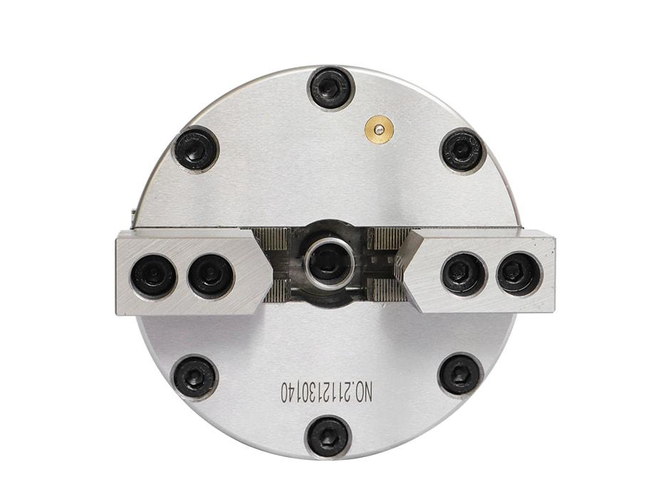
2-Jaw Solid Pneumatic Chuck
The solid-center design is used when through-spindle feeding is not required. It is suitable for balanced clamping of shaped parts.
Clean compressed-air clamping for CNC turning, vertical fixtures and fast part changeover.
KORRETTO pneumatic chucks use clean compressed air to clamp and release workpieces without a hydraulic oil circuit. They are suitable for CNC lathe workholding applications where the factory has stable air supply, needs faster part changeover, or wants to reduce the risk of hydraulic oil leakage around the work area. This range covers 2-jaw, 3-jaw, 4-jaw, solid, semi-through-hole, through-hole, vertical and front-mounted pneumatic chucks, along with related pneumatic collet chuck solutions.
These pneumatic chucks are used for CNC turning, vertical workholding and pneumatic clamping. Choose by jaw number, solid or through-hole structure, spindle arrangement, workpiece shape, available air pressure and required clamping force. Clamping force and maximum speed must be checked against the technical data for each model.
The solid-center design is used when through-spindle feeding is not required. It is suitable for balanced clamping of shaped parts.
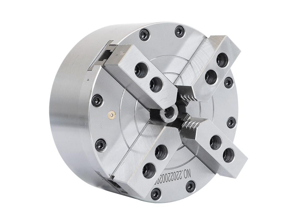
Four jaws help support non-round workpieces. Setup and inspection time should be considered in the production cycle.
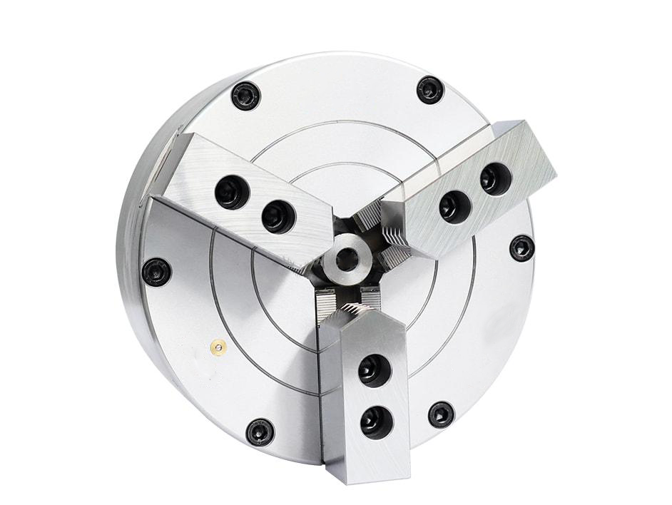
A practical 3-jaw pneumatic chuck for pneumatic clamping. Confirm gripping range, spindle interface, air pressure and required clamping force.
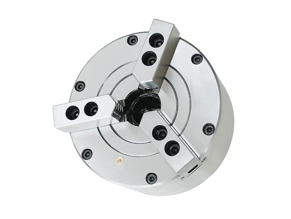
Used when a full through-hole design is not required but the workpiece or process needs limited internal clearance.
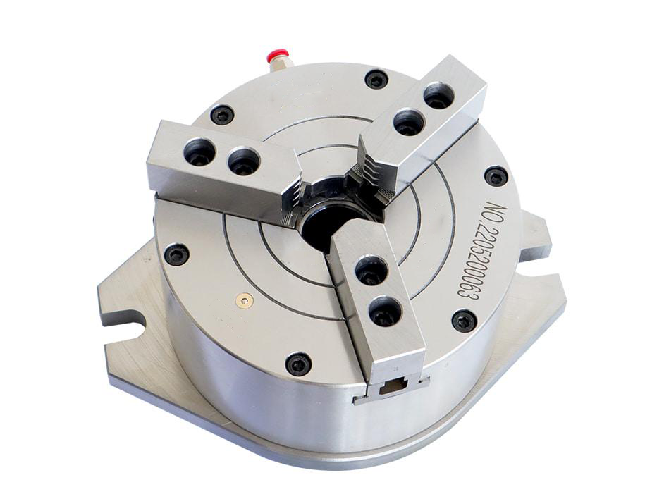
Suitable for vertical or fixed workholding stations where a through-hole and side air supply are required.
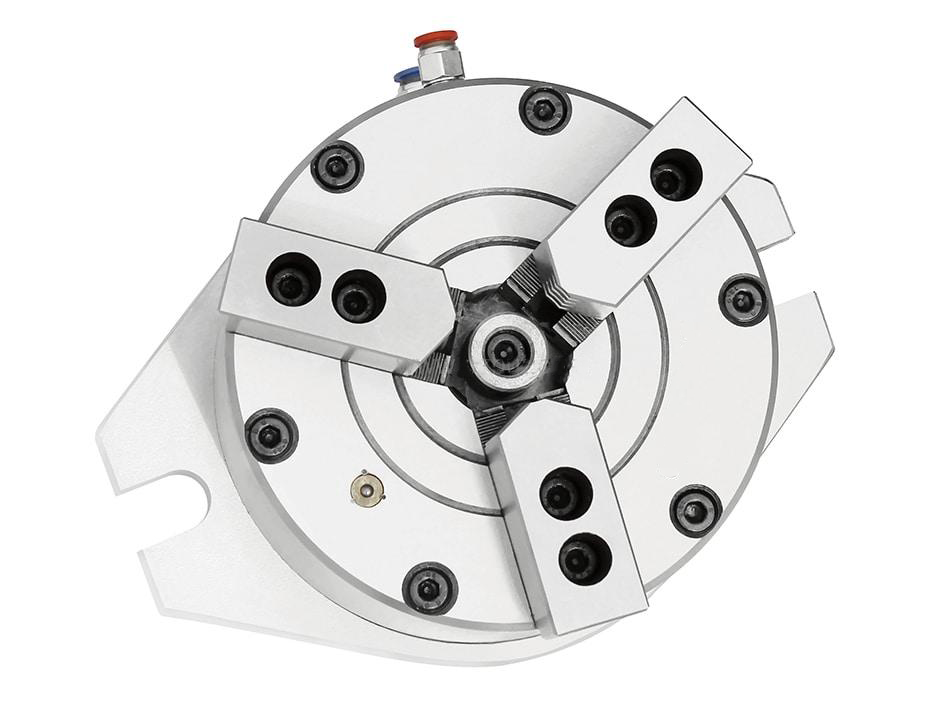
Used when a compact vertical pneumatic chuck is needed and the workpiece does not need to pass through the center.
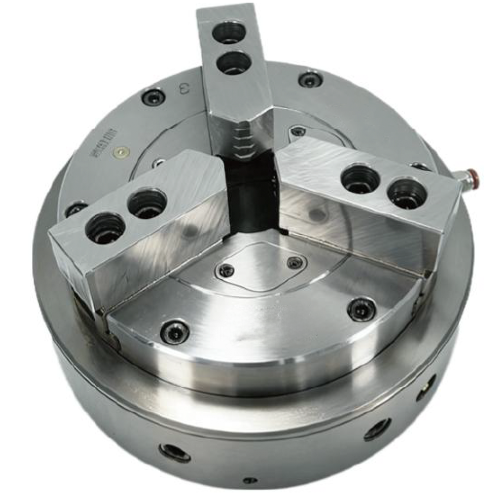
Mounted at the spindle end with a through-hole structure. Selection should follow the chuck drawing, stroke, air pressure and spindle interface requirements.
Pneumatic collet chucks and fixed collet units are used when the workpiece is better held by a collet-type mechanism or when the clamping unit is installed on a fixed station instead of a rotating spindle.
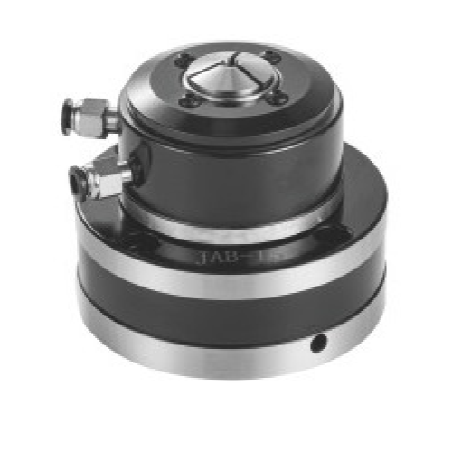
Used where fast clamping and clean air operation are required. It should be evaluated together with through-hole size and bar feeding requirements.
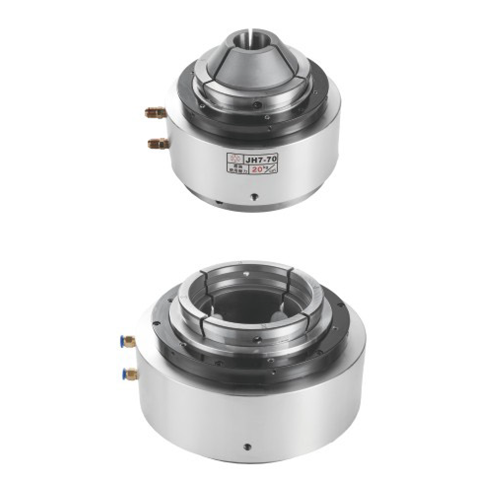
Helps reduce overhang at the spindle nose and can be selected when machine space and maintenance access are important.
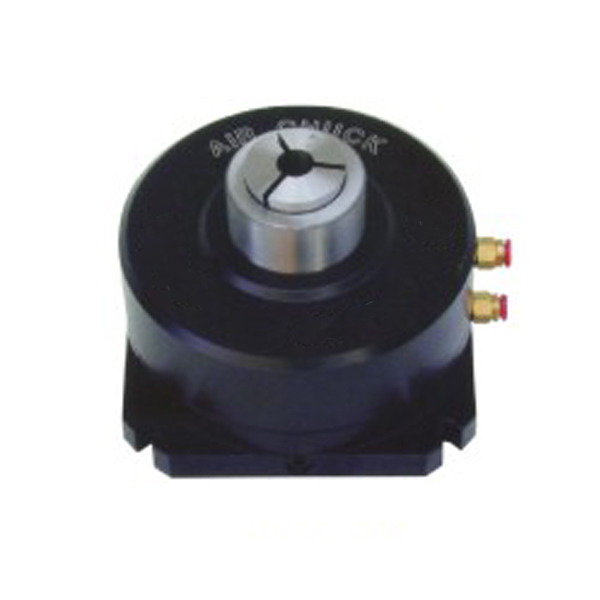
Used where the clamping unit is mounted to a fixed work station. Confirm mounting holes, piping direction and available air or hydraulic supply.
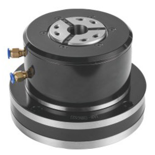
Confirm the clamping range, collet type, pressure, speed and machine interface against the JAB-SK technical data.
Send the workpiece drawing, machine interface, available air pressure, required cycle time, cutting load and automation requirements. We can help check whether a pneumatic chuck, hydraulic chuck, collet chuck or another workholding solution is more suitable.
Submit Your Project- Stable, clean and dry compressed-air supply is available.
- The process requires fast clamping and release.
- The work area needs to reduce hydraulic oil leakage risk.
- Cutting load is moderate and the required clamping force can be met with air pressure.
- Heavy interrupted cutting or higher clamping force: check Hydraulic Chucks.
- Manual setup and low automation demand: check Manual Chucks.
- Thin-wall or easily marked workpieces: check Rubber-Flex Collets, Collet Chucks or Diaphragm Chucks.
- Internal bore location: check Expanding Mandrels.
| Requirement | Start with |
|---|---|
| General short parts with pneumatic external clamping | 3-Jaw Solid Pneumatic Chuck |
| Symmetric shaped parts or two-point clamping | 2-Jaw Solid Pneumatic Chuck |
| Square or four-sided parts | 4-Jaw Solid Pneumatic Chuck |
| Partial bore clearance without full through-hole passage | 3-Jaw Semi-Through-Hole Pneumatic Chuck |
| Vertical fixture with through-hole requirement | 3-Jaw Vertical Through-Hole Pneumatic Chuck |
| Vertical fixture for short parts | 3-Jaw Vertical Solid Pneumatic Chuck |
| Lathe spindle-end through-hole clamping | Front-Mounted Through-Hole Pneumatic Chuck |
| Bar stock or collet-type clamping | High-Speed Pneumatic Collet Chuck / Front-Mount Collet Chuck |
| Requirement | Related solution |
|---|---|
| Higher clamping force or heavy cutting | Hydraulic Chucks |
| Simple wrench-operated setup | Manual Chucks |
| Thin-wall or easily marked external clamping | Rubber-Flex Collets / Collet Chucks / Diaphragm Chucks |
| Internal bore location | Expanding Mandrels |
| Face clamping, pipe-thread clamping or special workpieces | Application-Specific Power Chucks |
| Fixed table workholding | Machine Vises / Fixed Collet Chucks |
A pneumatic chuck requires stable, clean and dry compressed air. Water, oil mist and particles can affect valves, seals and clamping repeatability.
A pneumatic chuck uses compressed air to clamp and release the workpiece. In a chuck with a built-in cylinder, the piston pushes or pulls a wedge mechanism inside the chuck body, moving the jaws or collet to clamp and release the part. On a CNC lathe, the air line is usually connected to the rear of the chuck and then to a pneumatic rotary joint mounted at the back of the spindle.
Some pneumatic chuck systems use a power chuck connected to a rotary pneumatic cylinder, which works in a similar way to a hydraulic power chuck system but uses compressed air instead of hydraulic pressure.
For stationary use on CNC milling machines, drilling machines, or fixture plates, the chuck often has a built-in cylinder. The air line is usually connected from the side, but when several chucks are mounted on one fixture plate, the air path can also be routed through the bottom of the chuck.
Keep supply pressure within the selected model’s published range and verify its actual clamping force against workpiece diameter, material, cutting load, jaw position, speed and chuck data. Interrupted or heavy cutting requires a model-specific review of force reserve, retention method and machine safety system; the pneumatic category alone does not establish suitability. A hydraulic chuck may be preferred when the machine requires a hydraulic system, a different mounting structure or a larger continuous force reserve.
Yes. Pneumatic chucks can be used on CNC lathes when the spindle interface, through-hole or solid chuck structure, air supply, speed and clamping force are properly matched.
Choose a pneumatic chuck when clean air, fast clamping and reduced oil leakage risk are important. Choose a hydraulic chuck when higher clamping force, longer holding time or heavier cutting loads are required.
A solid chuck has no center through-hole and is used for short parts. A semi-through-hole chuck allows the workpiece to extend into the center hole of the chuck, but not through the spindle bore. A through-hole chuck allows bar, tube or long workpieces to pass through the chuck and into the spindle.
For KORRETTO models specified with a self-locking function, confirm the exact locking principle, reverse-pressure release circuit, check valve and permitted holding conditions for that model. Do not assume every pneumatic chuck in this category retains full clamping force after air loss. Clean, dry and stable compressed air and the machine’s safety interlocks remain necessary.
Pneumatic jaw chucks are better for parts that need jaw clamping or a specific jaw arrangement. Pneumatic collet chucks use a collet mechanism and are often selected for bar stock, smaller diameters, fast clamping, quick release and repeat production.