High-speed pneumatic collet chuck for fast, repeatable clamping of round workpieces.
High-Speed Pneumatic Collet Chuck
KORRETTO high-speed pneumatic collet chuck uses compressed air for clamping and release in collet-style workholding. It is suitable for round parts, shafts, sleeves and repeat CNC collet chuck applications where fast actuation, compact structure and repeat clamping are required.
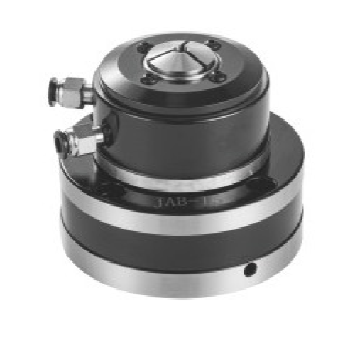
Product Overview
The high-speed pneumatic collet chuck is used where a round workpiece needs fast air-actuated collet clamping. Compared with a jaw chuck, a collet chuck provides more uniform contact around the clamping diameter. Compared with hydraulic systems, pneumatic actuation can be simpler for light to medium clamping loads and repeat collet clamping cycles.
JAW High-Speed Pneumatic Collet Chuck is the higher-precision upgraded version of the JAB series. It is selected when the application requires fast, repeatable collet clamping with higher positioning accuracy. Compare the JAB and JAW series according to workpiece diameter, clamping range, required speed, actuator layout and machine interface.
Key Features
| Feature | Description |
|---|---|
| Pneumatic actuation | Uses compressed air for clamping and release. |
| High-speed collet workholding | Suitable for rotary applications requiring speed and repeatability. |
| Uniform round-part contact | Collet clamping supports round shafts, sleeves and small precision parts. |
| Compact structure | Useful where a standard chuck is too large or heavy. |
| Different from BK pneumatic chucks | This is a collet chuck page, not a pneumatic jaw chuck page. |
Typical Applications
- Round workpieces
- Shaft and sleeve clamping
- High-speed rotary clamping
- Light to medium cutting conditions
- Repeat pneumatic collet workholding
- Many of these workholding systems are used together with precision machined parts in CNC manufacturing.
Technical Data for High-Speed Pneumatic Collet Chucks
Use the drawing and parameter tables to check collet range, mounting dimensions, air pressure, clamping stroke, maximum speed, weight and compatible spindle or fixture layout.
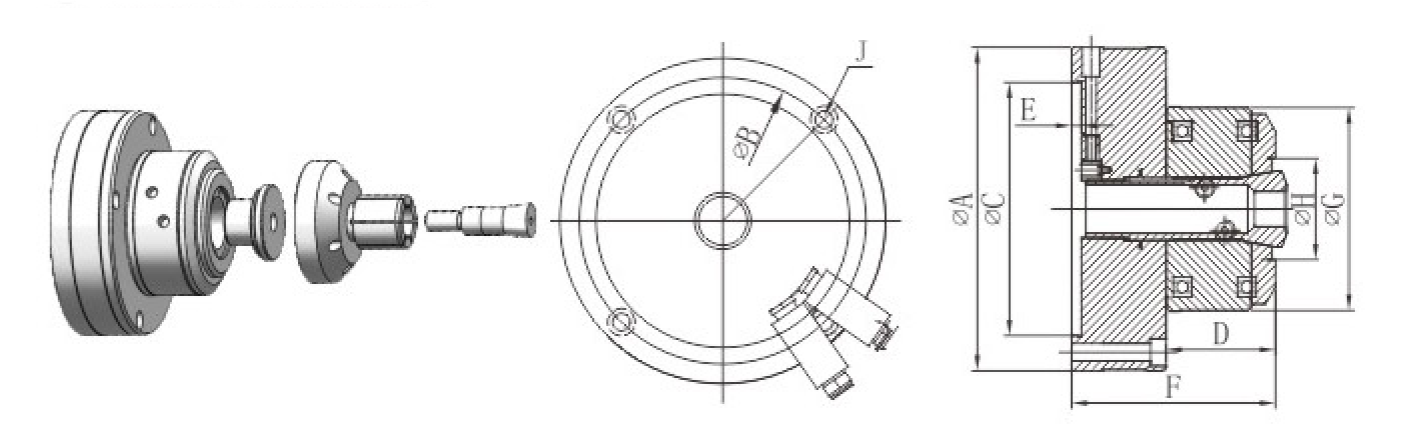
| Model | ΦA | ΦB | ΦC(H6) | D | E | F | ΦG | ΦH | J | Max. Speed (r/min) | Piston Stroke (mm) | Clamping Stroke (mm) | Max. Torque (N·m) | Operating Pressure (kg/cm²) | Clamping Range | Matching Collet | Weight (kg) | Clamping Type |
|---|---|---|---|---|---|---|---|---|---|---|---|---|---|---|---|---|---|---|
| JAB-15 | 100 | 84 | 70 | 40 | 5 | 80 | 71 | 30 | 4-M6 Countersunk Holes | 4000 | 4 | 1.5–2 | 3 | 3–8 | Φ2–14 | YB-15 | 3.2 | Front-Push |
| JAB-25 | 166 | 147 | 130 | 48 | 5 | 107 | 106 | 52 | 4-M8 Countersunk Holes | 4000 | 4 | 1.5–2 | 15 | 3–8 | Φ5–25 | YB-25 | 9.5 | Front-Push |
| JAB-40 | 187 | 168 | 150 | 50 | 5 | 115 | 133 | 72 | 4-M8 Countersunk Holes | 4000 | 4 | 1.5–2 | 30 | 3–8 | Φ5–40 | 16C | 13.5 | Front-Push |
| JAB-60 | 220 | 203 | 170 | 56 | 5 | 132 | 169 | 98 | 4-M8 Countersunk Holes | 3000 | 4 | 1.5–2 | 35 | 3–8 | Φ5–60 | 20C | 20.5 | Front-Push |
Related Collet Chuck Pages
FAQ
What is a high-speed pneumatic collet chuck used for?
It is used for air-actuated collet clamping of round workpieces, shafts and sleeves where quick clamping, release and high-speed rotation are required.
Is this a general pneumatic chuck?
No. This is a pneumatic collet chuck. It uses collet-style clamping rather than standard jaw clamping.
How is this different from the JAW High-Speed Pneumatic Collet Chuck series?
The JAW series is the higher-precision upgraded version of the JAB high-speed pneumatic collet chuck. It is selected when the application needs fast, repeatable collet clamping with higher positioning accuracy. Final selection should be based on workpiece diameter, clamping range, required speed, actuator layout and machine interface.
What should be checked before selection?
Check the workpiece diameter, collet type, air pressure, speed, clamping force, spindle interface and cutting load.
Can this chuck replace a hydraulic collet chuck?
It depends on required clamping force, speed, cycle time and machine layout. Pneumatic and hydraulic actuation should be selected according to the process.
How should collet-chuck runout and repeatability be checked?
Distinguish chuck-body mounting runout from workpiece runout and repeatability. Install the chuck according to the machine and product instructions, then measure the body at the specified location. Use a clean, correctly seated collet matched to the actual workpiece diameter, and measure a test bar with a stated diameter, overhang, air pressure and clamping cycle. Record repeatability over repeated clamps under the same conditions. Do not claim near-zero runout or adjust the body by striking it unless a model-specific manufacturer procedure provides that method and tolerance.
Next, check the collet and the actual clamping condition. Make sure the collet is clean, seated correctly and matched to the workpiece diameter. If soft jaws or jaw-type fixtures are used in the same setup process, the gripping surface should be bored after the chuck is mounted. Because there is always some clearance between the chuck body and the jaws, a very small taper may sometimes be added when boring the gripping arc to compensate for jaw opening under load.
For the best repeat accuracy on the same workpiece diameter, clamp a test bar after the flange and chuck have been aligned. Check the test bar with a dial indicator. If further adjustment is needed, slightly loosen the chuck mounting bolts and gently tap the high point of the chuck outside diameter with a copper rod until the test bar runout is minimized. After tightening the bolts again, the chuck will usually repeat best when clamping workpieces with the same diameter and similar clamping conditions.