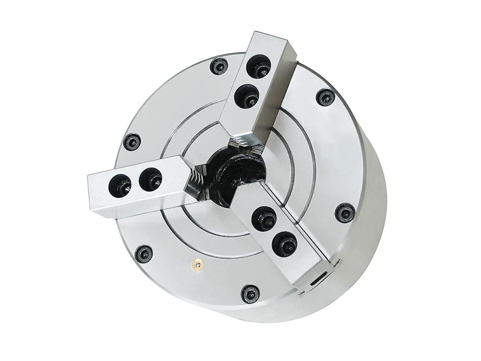
Three-jaw solid pneumatic chuck for short round parts, compressed-air clamping and repeat loading.
BK-SQ 3-Jaw Solid Pneumatic Chuck
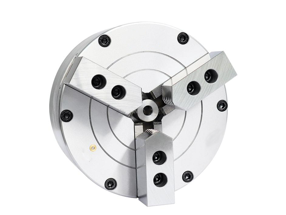
KORRETTO BK-SQ 3-jaw solid pneumatic chuck is used for round workpieces, short blanks, sleeves and disc-type parts that do not require through-spindle passage. The pneumatic structure supports quick clamping and release by compressed air, making it suitable for repeated loading, light to medium cutting conditions, round workpiece clamping and automation-friendly clamping layouts.
Product Overview
The BK-SQ 3-jaw solid pneumatic chuck is a standard solid-center pneumatic chuck for external clamping of round or near-round workpieces. It is selected when the part is loaded as an individual blank rather than passed through the spindle, and when compressed air clamping is preferred over a hydraulic circuit.
This page only covers the BK-SQ 3-jaw solid pneumatic chuck. It does not include semi-through-hole, vertical through-hole, vertical solid or front-mounted through-hole pneumatic chuck structures.
Key Features
| Feature | Description |
|---|---|
| 3-jaw pneumatic clamping | Suitable for round and near-round workpieces. |
| Solid-center structure | Used for short blanks and parts without through-spindle requirements. |
| Fast pneumatic actuation | Supports quick clamping and release through compressed air. |
| Repeat production use | Suitable for repeated loading and batch machining. |
| Compact workholding option | Useful where hydraulic systems are not required or not available. |
Typical Applications
- Short round blanks
- Sleeve-type workpieces
- Disc-type parts
- Repeat pneumatic clamping
- CNC lathe and fixture applications without through-hole requirements
Technical Data for 3-Jaw Solid Pneumatic Chucks
Use the drawing and parameter tables to check chuck size, mounting dimensions, jaw stroke, air pressure, clamping force, maximum speed, weight and workpiece compatibility.
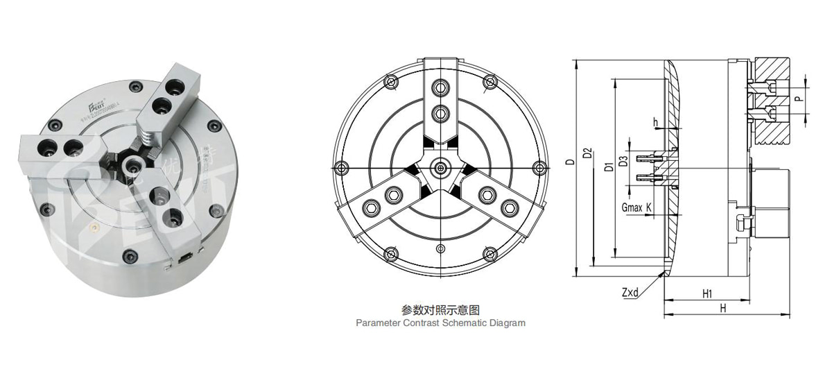
| Model | D | D1 | D2 | d | H | H1 | h | Gmax K | Z × d | Power Wedge Serration | Matching Jaw Model |
|---|---|---|---|---|---|---|---|---|---|---|---|
| BK110SQ | 115 | 72 | 102 | 22 | 106 | 81 | 3 | 17 | 3-M8 | 1×53° | BK110Z1 |
| BK130SQ | 135 | 95 | 108 | 25 | 123 | 92 | 4.5 | 15.5 | 3-M8 | 1×53° | BK130Z1 |
| BK160SQ | 172 | 130 | 142 | 25 | 129 | 93 | 4.5 | 17.5 | 3-M8 | 1×53° | BK160Z1 |
| BK200SQ | 210 | 165 | 180 | 32 | 133 | 97 | 5 | 17 | 3-M10 | 1×53° | BK200Z1 |
| BK250SQ | 250 | 206 | 226 | 40 | 145 | 99 | 5 | 17 | 3-M12 | 1×53° | BK250Z1 |
| BK320SQ | 325 | 270 | 290 | 50 | 177 | 116 | 5 | 29 | 6-M12 | 1.5×60° | BK320Z2-60 |
| BK400SQ | 400 | 340 | 368 | 60 | 212 | 141 | 6 | 33 | 6-M16 | 1.5×60° | — |
| BK500SQ | 500 | 440 | 465 | 70 | 256 | 183 | 6 | 34 | 6-M16 | 3×60° | — |
| Model | Jaw Stroke t (Diameter, mm) | Max. Clamping Force (kN) | Max. Expanding Force (kN) | Allowable Pressure (MPa) | Max. Speed (r/min) | Clamping Range (mm) | Expanding Range (mm) | Net Weight (kg) |
|---|---|---|---|---|---|---|---|---|
| BK110SQ | 3.7 | 14 | 7.4 | 0.4–0.8 | 4800 | 2–115 | 15–120 | 6 |
| BK130SQ | 3.2 | 21.2 | 11.5 | 0.4–0.8 | 4800 | 2–130 | 20–140 | 9 |
| BK160SQ | 3.7 | 36.5 | 19.3 | 0.4–0.8 | 4200 | 2–170 | 20–180 | 14 |
| BK200SQ | 4.2 | 53.8 | 30.7 | 0.4–0.8 | 5000 | 5–210 | 20–240 | 22.6 |
| BK250SQ | 4.8 | 73.2 | 46.9 | 0.4–0.8 | 2800 | 10–260 | 30–280 | 33.4 |
| BK320SQ | 8.5 | 116.6 | 78.3 | 0.4–0.8 | 2300 | 10–350 | 40–360 | 73 |
| BK400SQ | 11.5 | 158.2 | 102.9 | 0.4–0.8 | 1000 | 15–420 | 50–430 | 128 |
| BK500SQ | 20 | 203.9 | 138.6 | 0.4–0.8 | 1000 | 20–520 | 50–530 | 200 |
Related Pneumatic Chuck Pages
FAQ
What is the BK-SQ 3-jaw solid pneumatic chuck used for?
It is used for round workpieces, short blanks, sleeves and disc-type parts that need 3-jaw pneumatic clamping and do not require through-spindle passage.
How is it different from a hydraulic chuck?
A pneumatic chuck uses compressed air for clamping and release, while a hydraulic chuck uses hydraulic pressure. The correct choice depends on the required clamping force, machining load and production cycle.
How should solid, semi-through-hole and through-hole structures be selected?
Choose a solid pneumatic chuck when the part does not need center passage. Choose a semi-through-hole chuck when partial internal clearance is needed. Choose a through-hole chuck when bar, tube or long workpieces must pass through the center.
What air pressure should be confirmed?
Check the available operating air pressure, pressure stability and the clamping force margin required for the workpiece.
Can it be used for automated loading and unloading?
Yes. Pneumatic clamping can support repeated loading and unloading when the air circuit, part transfer method and safety controls are properly matched.
What machine or spindle interface should be checked?
Check the mounting interface, bolt pattern, jaw stroke, installation space and the required spindle or fixture arrangement before confirming the chuck.
What should be checked before installation?
Check jaw stroke, clamping diameter, workpiece support condition, air connection and interference envelope before installation.
What information is needed for quotation?
Provide the workpiece drawing, material, diameter, clamping length, operating air pressure, machine layout, target speed and required clamping force.