Long oil pipes, casing and tubing
Feed the pipe through the spindle and grip close to the end. Use this arrangement for pipe-end threading, facing and chamfering.
Pipe-end chuck for oil pipe threading, casing, tubing and front-mounted pneumatic workholding.
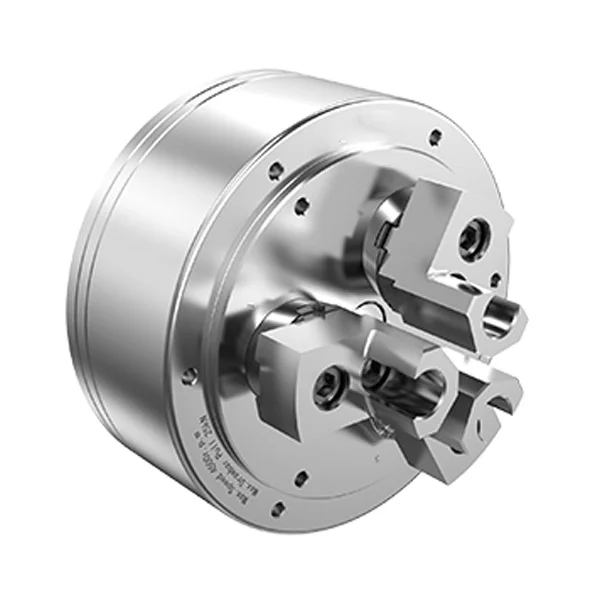
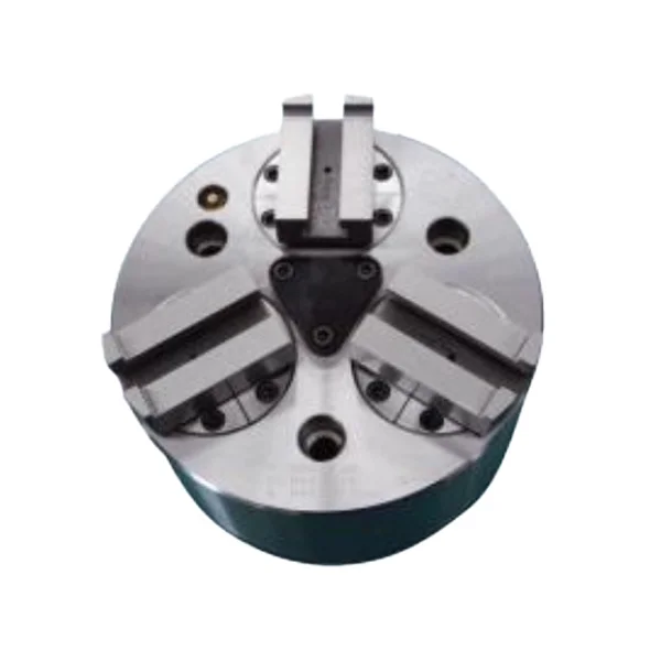
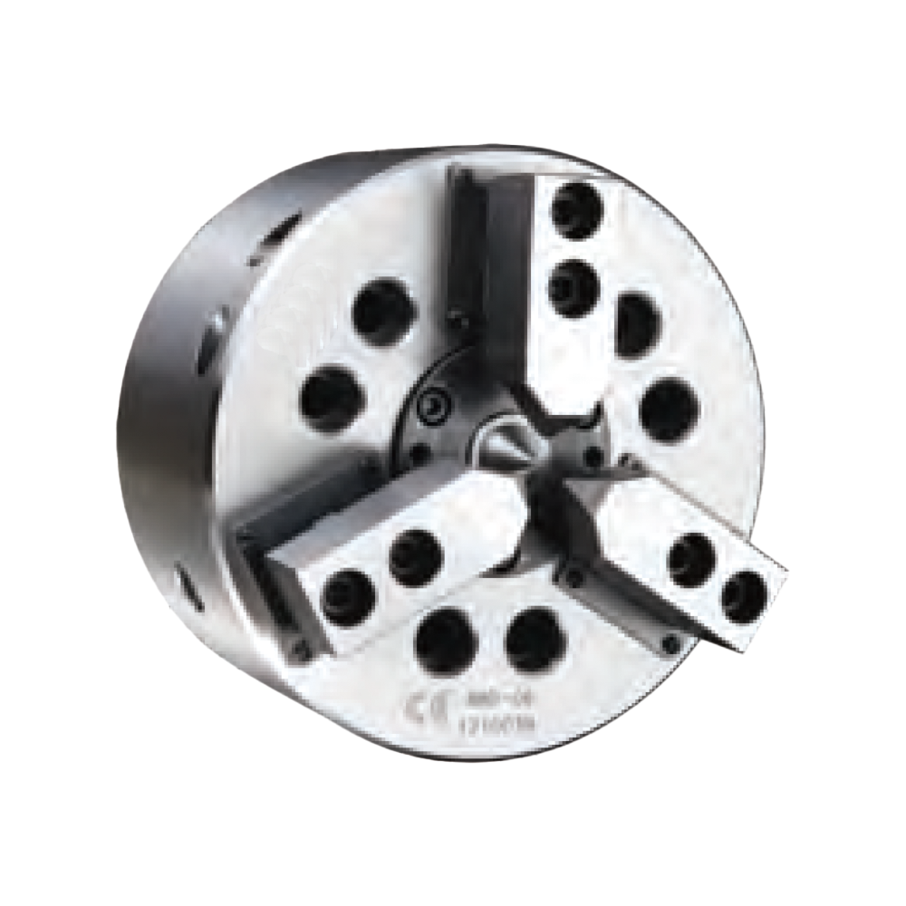
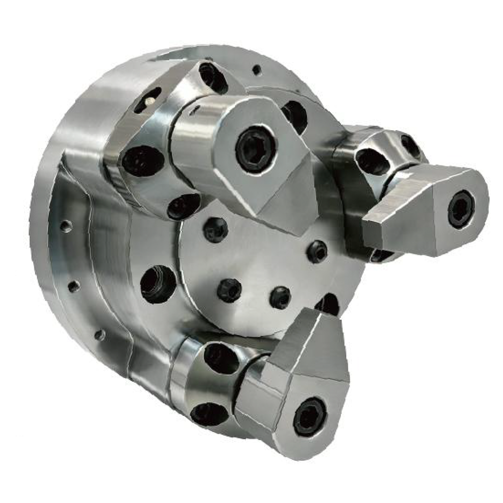
The K53 front-mounted pneumatic chuck holds long tubular workpieces for pipe-end threading. Its air cylinder is built into the chuck body. The pipe passes through the central bore, and three jaws grip its outside diameter. Long-pipe lathes can use one chuck at the front of the spindle and another at the rear.
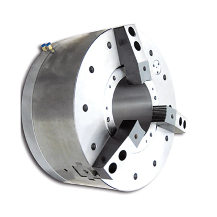
An oil pipe thread chuck holds a tubular workpiece on a pipe-threading lathe. The jaws grip the outside of the pipe. The pipe end stays clear for threading, facing and chamfering. The K53 uses a front-mounted pneumatic design.
This design is also called a pneumatic front-end chuck or an air-operated self-contained chuck. The cylinder sits inside the chuck body and drives the clamping movement there. The central bore leaves room for the pipe to pass through the spindle.
Workshop photos: See the finished K53 chucks and customer batch
This customer video shows the K53 installed on a lathe. You can see the three-jaw chuck, the tubular workpiece and the cutting operation at the pipe end. Use the video to understand the setup, then check the drawings and model tables below.
These workshop photos show finished chucks from the same series. The central bore, three jaws and chuck body are easy to see. Open the production blog for more photos of the batch.
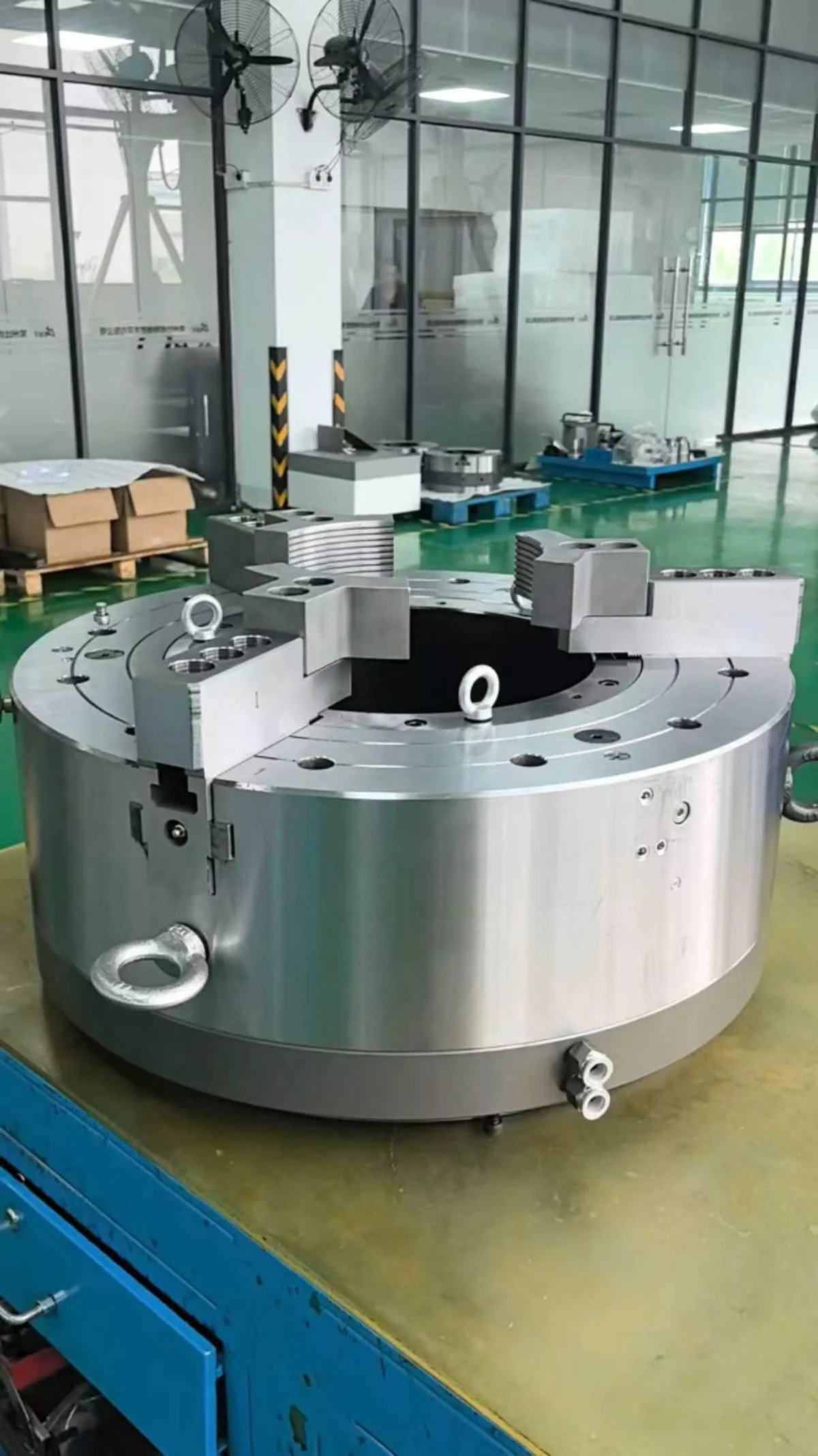
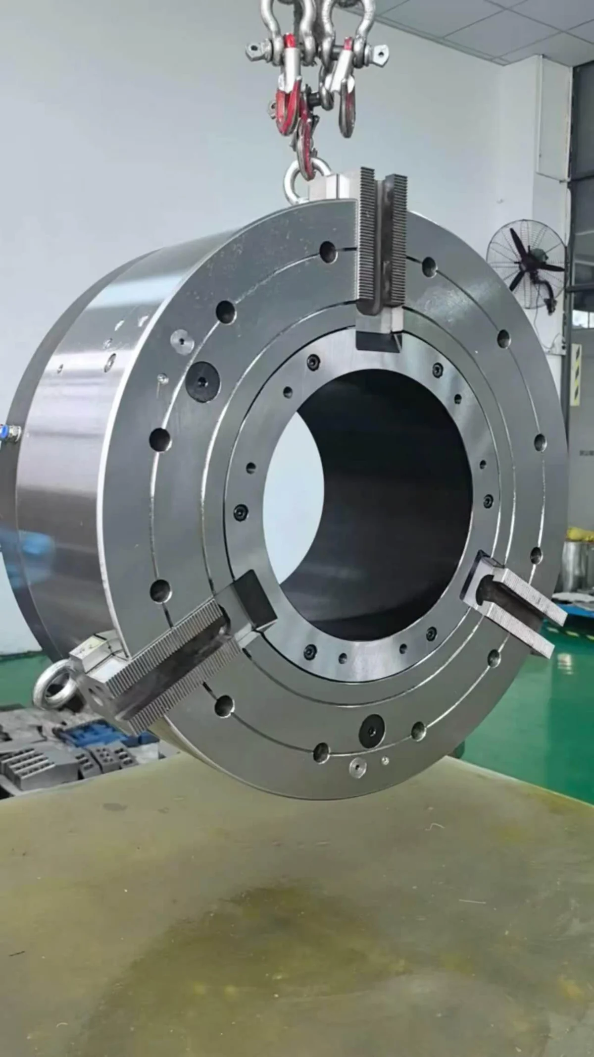
Workshop photos: See the finished K53 chucks and customer batch
Use the drawing and parameter tables to check chuck size, pipe clamping range, mounting dimensions, pneumatic pressure, clamping force, speed, inertia and matching machine conditions.

Use this drawing to confirm installation dimensions and technical parameters.
| Model | A | A1 | B | C (H6) | D | E | F | M |
|---|---|---|---|---|---|---|---|---|
| 350 | 380 | 315 | 192 | 235 | 275 | 7 | 115 | 6-M12 |
| 400S | 467 | 400 | 194 | 310 | 374 | 8 | 152 | 9-M12 |
| 400 | 223 | 150 | ||||||
| 460 | 238 | 181 | ||||||
| 500 | 510 | 313(338) | 325(300) | 360(330) | 10.5 | 205 | 12-M16 | |
| 570 | 570 | 500 | 280 | 415 | 474 | 8 | 12-M12 | |
| 570A | 230 | |||||||
| 600 | 605 | 535 | 450 | 508 | 280 | |||
| 630 | 685 | 610 | 305.5 | 510 | 580 | 325 | ||
| 730 | 730 | 658 | 301.5 | 560 | 630 | 10.5 | 355 | 12-M16 |
| 850 | 850 | 755 | 352 | 700 | 745 | 8 | 375 | |
| 900 | 900 | 440 | ||||||
| 1000 | 1000 | 850 | 330 | 815 | 10 | 560 | ||
| 1150 | 1150 | 1060 | 352 | 800 | 1000 | 660 |
Use this drawing to confirm installation dimensions and technical parameters.
| Model | Single Jaw Stroke (mm) | Clamping Force (Air Pressure 0.5 MPa) kN (kgf) | Max. Speed (r/min) | Moment of Inertia (kg·m2) | Weight (kg) | Pressure MPa (kgf/cm2) |
|---|---|---|---|---|---|---|
| 350 | 13+7 | 62(6326) | 3000 | 1.62 | 110 | 0.2-1(2-10) |
| 400S | 7 | 130(13265) | 1700 | 5.6 | 154 | |
| 400 | 13+7 | 1300 | 6.5 | 200 | ||
| 460 | 110(11220) | 9.8 | 190 | |||
| 500 | 17+7 | 140(14286) | 15.5 | 298 | ||
| 570 | 17+8.5 | 160(16326) | 16.4 | 340 | ||
| 570A | 140(14286) | 16.1 | 325 | |||
| 600 | 160(16326) | 1100 | 19 | 360 | ||
| 630 | 180(18367) | 900 | 28 | 520 | ||
| 730 | 15+10 | 190(19388) | 800 | 44.2 | 583 | |
| 850 | 13.4+12 | 200(20408) | 750 | 71.2 | 970 | 0.3-1(3-10) |
| 900 | 190(19388) | 700 | 105 | 980 | ||
| 1000 | 15+10.4 | 170(17347) | 450 | 150 | 960 | |
| 1150 | 230(23470) | 400 | 194 | 1890 |
Compressed air enters the built-in cylinder and moves the piston.
The internal drive transfers the piston movement to the three jaws. They move radially towards the pipe.
The jaws contact and grip the outside diameter. The exposed pipe end leaves room for the cutting tool.
After machining, stop the spindle. Switch the air circuit to retract the jaws, then remove or reposition the pipe.
Air operates the clamping mechanism. The machine spindle rotates the chuck and workpiece during cutting. These are separate functions.
The long pipe passes through the spindle. The front chuck grips near the cutting end. The rear chuck grips the pipe behind the spindle. Two gripping points help control the pipe axis and reduce movement compared with holding the pipe only at the front.
Align the centres of both chucks during installation. Set the gripping positions and the exposed pipe length. Use rollers or a support stand for the pipe extending outside the machine.
The jaws first travel quickly across the open gap. This reduces the time spent approaching the pipe. As the jaws get close to the workpiece, they slow down and complete the grip.
The two stages are rapid approach and slower clamping. They describe jaw movement, not spindle speed. When changing pipe sizes, check the outside diameter, jaw position and available single-jaw stroke together.
The model table below lists the stroke for each size. Size 350 is listed as 13+7 mm; 400S is listed as 7 mm. Use the row for the chosen model rather than assuming every model has the same stroke.
Feed the pipe through the spindle and grip close to the end. Use this arrangement for pipe-end threading, facing and chamfering.
Grip the coupling outside diameter and leave the bore accessible. Set the gripping length so the internal threading tool has room to enter and withdraw.
Hold drill rods and long tubes for threading at their ends or connection areas. Choose the chuck around pipe diameter, wall thickness and length. Then arrange the front and rear grips and external supports.
| Item | K53 front-mounted pipe chuck | General pneumatic chuck selection |
|---|---|---|
| Workpiece | Long oil pipes, couplings, drill rods and other tubes. | Usually selected around the size and gripping method of a general turning job. |
| Cylinder | Built into the chuck body. | Internal and external cylinder designs exist; check the actual product. |
| Machine layout | Can use front and rear spindle chucks for long pipe. | A single chuck is common; long workpieces need additional support. |
| Pipe passage | Large through-bore and spindle passage are central to selection. | Bore size depends on the product. Pneumatic actuation alone does not mean a large bore. |
| Jaw movement | Long travel, rapid approach and slower clamping; check the model row. | Check stroke and movement stages. They cannot be inferred from the word pneumatic. |
Send the outside diameter, wall thickness, length and thread drawing. Mark the gripping position and exposed pipe-end length.
Send the spindle bore, spindle nose or flange dimensions and space at both ends. Include photos of both mounting positions for a dual-chuck setup.
Give the air pressure, required jaw travel, machining speed and cutting operations. State whether rapid approach and slower clamping are needed.
It is used for clamping oil pipes, casing, tubing and other pipe ends during pipe threading, thread machining or related pipe-end operations.
The K53 uses compressed air and a cylinder built into the chuck body. A conventional hydraulic chuck uses hydraulic actuation. For long pipes, the K53 can be fitted at the front and rear of the spindle.
Confirm the pipe outside diameter, wall thickness, length, material and whether the workpiece is oil pipe, casing, tubing or another tubular part.
Check the machine model, spindle through-hole, spindle nose or mounting interface, available front-side space and the actuation layout before selection.
Provide the required clamping range, the pipe-end condition, the clamping position and whether the threading process changes the exposed pipe-end length.
Yes. It is commonly used for pipe-end threading production where the workpiece must pass through the spindle and be held securely at the pipe end.
Check the mounting dimensions, spindle through-hole, pneumatic pressure, pipe support condition, target speed and available installation space before installation.
Provide the pipe outside diameter, wall thickness, length, thread type, machine model, spindle through-hole, clamping position, pneumatic pressure and any photos or drawings of the current setup.
The front chuck grips near the cutting end. The rear chuck grips behind the spindle. These two points help control the long pipe axis. The pipe outside the machine also needs rollers or a support stand.
No. The jaws approach quickly, then slow down to clamp. The lathe controls spindle speed.
Compressed air moves the piston inside the chuck body. The internal drive transfers this movement to the jaws. The clamping movement takes place inside the chuck.