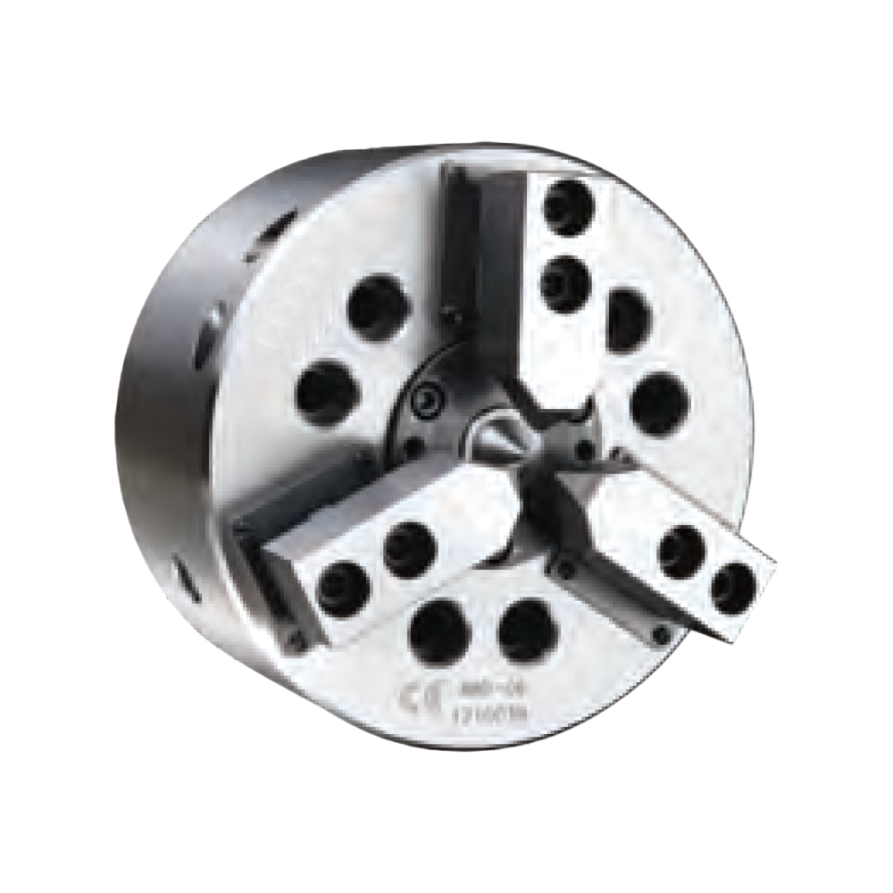
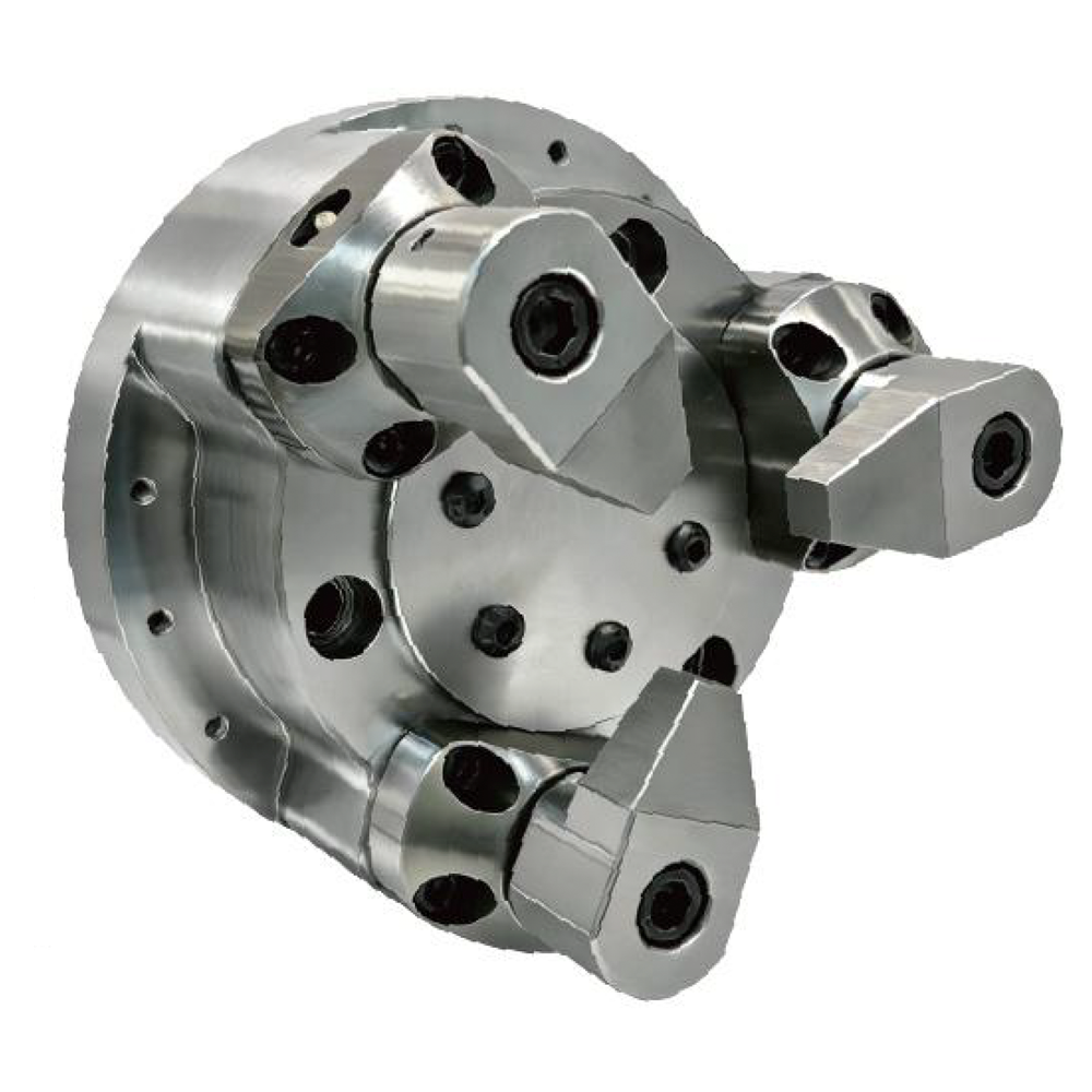
Special hydraulic power chuck for floating compensation on long shafts, slender parts and non-uniform blanks.
Floating Compensation Hydraulic Chuck
KORRETTO Floating Compensation Hydraulic Chuck is a application-specific power chuck for long shafts, slender parts and blanks where the outside diameter and center condition are not fully consistent. The floating compensation structure helps reduce extra loading caused by forced clamping on non-uniform workpieces.
Product Overview
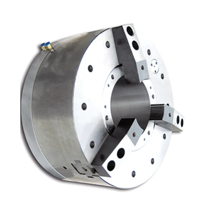
The Floating Compensation Hydraulic Chuck is used for long shafts, slender parts and blanks whose outside diameter, center hole or support condition is not fully consistent. Compared with a standard chuck, it is selected to reduce the extra effect of forced clamping on the workpiece.
It is suitable for CNC lathe workholding and special production applications where the workpiece condition varies from part to part. Selection should be based on workpiece length, center-hole condition, support method, clamping force, machine spindle interface and required machining accuracy.
Key Features
| Feature | Description |
|---|---|
| Floating compensation structure | Allows the chuck to adapt within a limited range to the actual workpiece condition. |
| Hydraulic actuation | Supports controlled clamping and release through a hydraulic chuck system. |
| Suitable for long and slender workpieces | Used for long shafts, slender parts and blanks that need support-aware clamping. |
| Helps reduce forced-clamping load | Useful when outside diameter and center condition are not fully consistent. |
| Special workholding use | Selected when standard hydraulic chucks cannot manage the workpiece condition well enough. |
Typical Applications
- Long shafts and slender parts
- Blanks with unstable outside-diameter condition
- Workpieces with center-hole and outside-diameter mismatch
- Parts used with tailstock support
- Special hydraulic chuck applications requiring compensation
Technical Data and Dimensions
Use the drawing and parameter tables to check chuck size, spindle nose, jaw stroke, hydraulic force, clamping force, maximum speed, mounting dimensions and workpiece compatibility. The values must be checked together with the machine spindle, drawbar and hydraulic cylinder conditions.
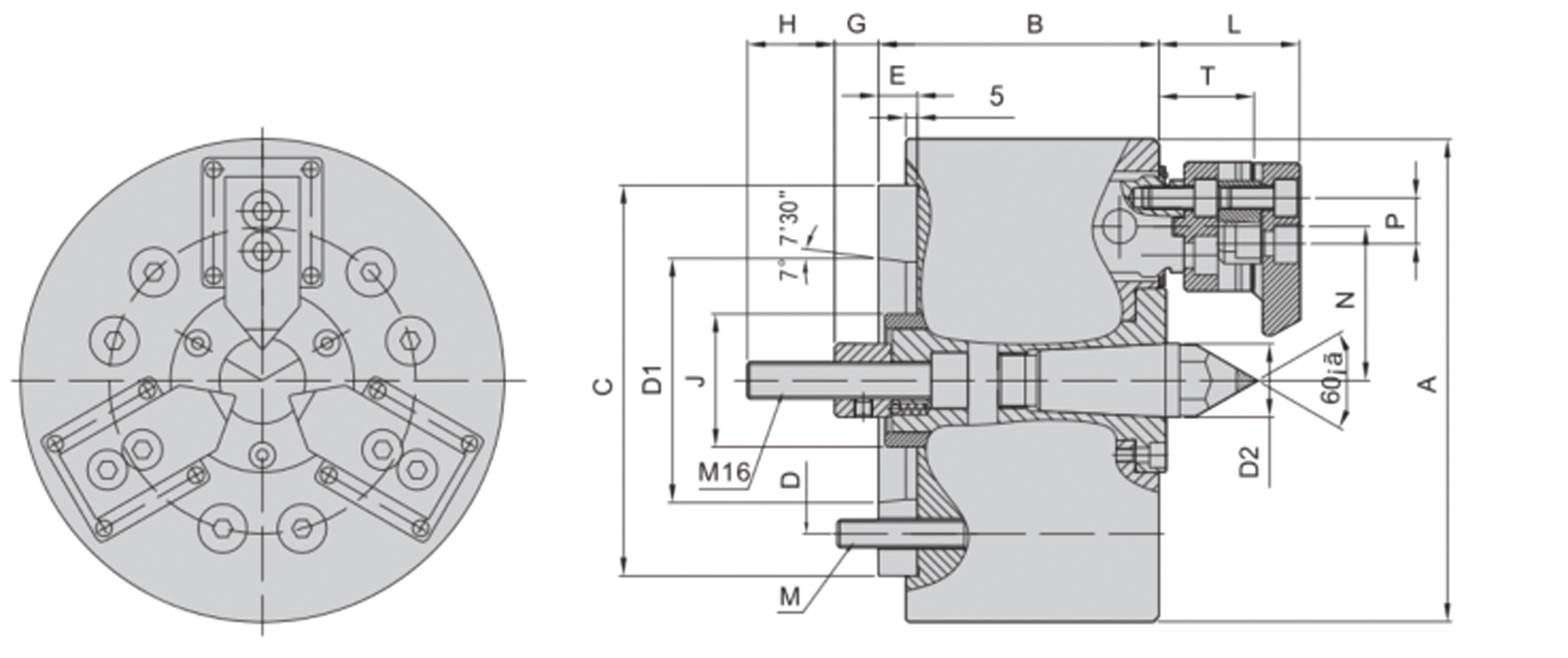
Use this drawing to confirm installation dimensions and technical parameters.
| Model | Spindle Nose | A | B | C (H6) | D | D1 | D2 | E | G | H | J | L | M | N | P | T |
|---|---|---|---|---|---|---|---|---|---|---|---|---|---|---|---|---|
| 3BD-06 | A5 | 168 | 116 | 140 | 104.8 | 82.56 | 24 | 15 | 4-20 | 38 | 50 | 52 | M10*120 | 55 | 14 | 34 |
| 3BD-08 | A6 | 210 | 127 | 170 | 133.4 | 106.38 | 32 | 17 | 9-29 | 38 | 58 | 61 | M12*125 | 67 | 20 | 41.5 |
| Model | Spindle Nose | Plunger Stroke (mm) | Jaw Stroke (mm) | Max. Pull kN (kgf) | Max. Clamping kN (kgf) | Max. Speed (r/min) | Clamping Range (mm) | Compensation Range (Diameter, mm) | Moment of Inertia (kg·m²) | Weight (kg) | Matching Cylinder | Max. Pressure MPa (kgf/cm²) |
|---|---|---|---|---|---|---|---|---|---|---|---|---|
| 3BD-06 | A5 | 16 | 13 | 14.7 (1500) | 25.0 (2550) | 3500 | 6–35 | 5 | 0.2 | 13 | 100 | 2.1 (21) |
| 3BD-08 | A6 | 20 | 18 | 19.6 (2000) | 34.3 (3500) | 3000 | 16–65 | 6 | 0.5 | 22 | 100 | 2.8 (28) |
Selection Notes
- Confirm workpiece length, rigidity and support method.
- Check the center-hole condition, outside-diameter condition and locating reference.
- Review jaw stroke, compensation range, hydraulic force and maximum speed.
- Confirm spindle nose, drawbar connection and cylinder compatibility.
- For thin-wall or easily deformed parts, also compare diaphragm chucks and rubber-flex collets.
Related Application-Specific Power Chuck Pages
FAQ
What workpieces is this Floating Compensation Hydraulic Chuck used for?
It is used for long shafts, slender parts, blanks with unstable outside diameter condition and workpieces where the center hole and outside diameter are not fully aligned.
How is it different from a standard hydraulic chuck?
A standard hydraulic chuck usually forces the workpiece toward the chuck center. A Floating Compensation Hydraulic Chuck can adapt within a limited range to the actual workpiece condition and reduce extra loading from forced clamping.
Can this chuck completely eliminate workpiece bending?
No. It is used to reduce the additional effect of clamping on the workpiece. The original bending condition, center-hole quality and support method still affect the machining result.
Does it always need to be used with a tailstock center?
Many long-shaft applications are used with a tailstock center, but the final support method depends on workpiece length, rigidity, clamping position and machining load.
Why should center-hole information be provided for selection?
The center-hole condition affects tailstock support and workpiece reference. If the center hole and outside diameter are not aligned, ordinary clamping can create extra deformation or machining error.
Is it suitable for batch production?
Yes, it can be suitable for batch production of stable workpiece types, but the compensation range should still be checked against the real blank condition and process requirement.
Can it directly replace a standard hydraulic chuck?
No. The spindle nose, drawbar, rotary hydraulic cylinder, clamping range and workpiece support method must be checked together, rather than replacing only by chuck diameter.
What information is needed for quotation?
Please provide the workpiece drawing, workpiece length, outside-diameter condition, center-hole requirement, tailstock support method, machine model, spindle nose and current clamping method.