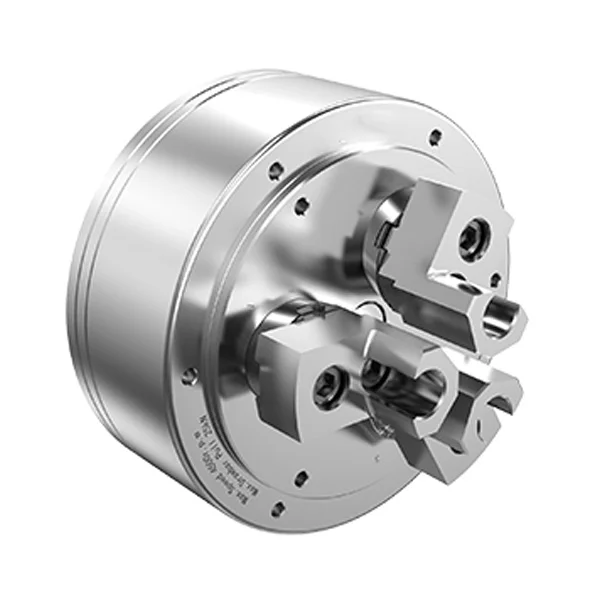
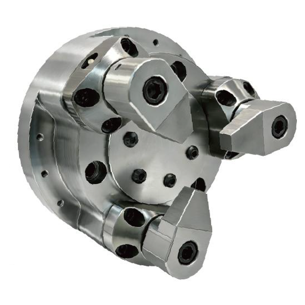
Special hydraulic power chuck for axial draw-down, end-face seating and repeat workpiece location.
Pull-Back Hydraulic Chuck
KORRETTO Pull-Back Hydraulic Chuck is a application-specific power chuck that pulls the workpiece toward a locating surface during clamping. The pull-back or draw-down action helps improve axial seating, repeat length control and workpiece location consistency for CNC lathe applications where radial clamping alone is not enough.
Product Overview
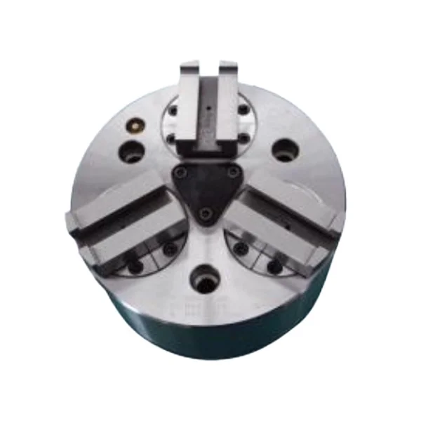
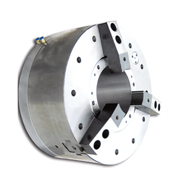
A pull-back hydraulic chuck combines radial clamping with axial seating action. During clamping, the workpiece is pulled toward the locating face, helping reduce axial variation between repeated loading cycles.
This page only covers the pull-back hydraulic chuck. It does not cover standard hydraulic chucks, general hollow hydraulic chucks or unrelated internal expansion structures from old templates.
Key Features
| Feature | Description |
|---|---|
| Pull-back / draw-down action | Pulls the workpiece toward a locating surface during clamping. |
| Improved axial seating | Helps improve repeat length control and end-face location. |
| Hydraulic actuation | Works with compatible hydraulic chuck and machine drawbar conditions. |
| Special locating applications | Useful when axial location is more important than standard radial holding alone. |
| CNC lathe use | Suitable for repeated loading and production clamping. |
Typical Applications
- Workpieces requiring end-face seating
- Parts requiring repeat length control
- CNC lathe axial locating applications
- Flange, sleeve or disc-type workpieces
- Jobs where radial clamping alone cannot control axial position
Technical Data and Dimensions
Use the drawing and parameter tables to check spindle nose, mounting dimensions, jaw stroke, pull-back stroke, allowable drawbar force, clamping force, maximum speed, weight and pressure range.
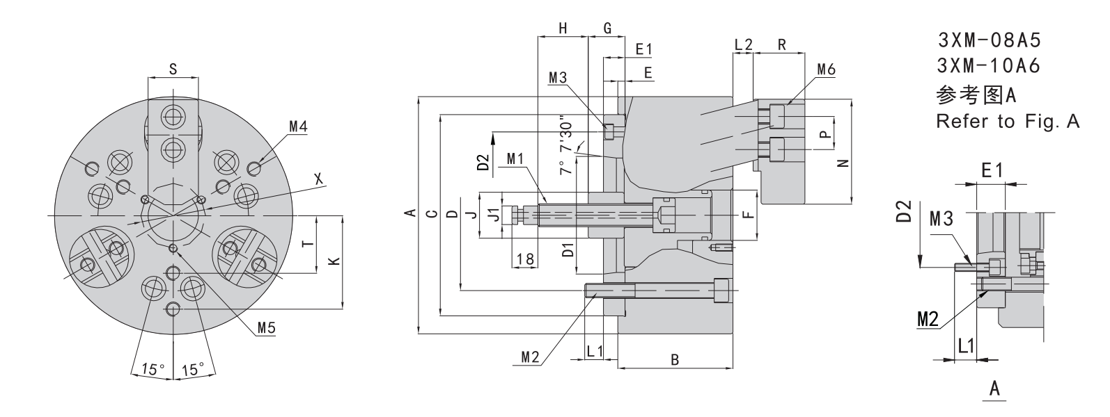
Use this drawing to confirm installation dimensions and technical parameters.
| Model | Spindle Nose | A | B | C (H6) | D | D1 | D2 | E | E1 | F | G | H | J | J1 | K | L1 | |
|---|---|---|---|---|---|---|---|---|---|---|---|---|---|---|---|---|---|
| max | min | ||||||||||||||||
| 3PB-06 | A5 | 165 | 85 | 140 | 104.8 | 82.56 | 116 | 5 | 15 | 35 | 30 | 15 | 35 | 32 | 13 | 55 | 13 |
| 3PB-08 | A5 | 210 | 100 | 170 | 133.4 | 104.8 | 23 | 45 | 27 | 7 | 38 | 37 | 16 | 75 | 17 | ||
| A6 | 106.38 | 150 | 17 | ||||||||||||||
| 3PB-10 | A6 | 254 | 110 | 220 | 171.4 | 133.4 | 25 | 55 | 31 | 11 | 41 | 48 | 20 | 85 | 19 | ||
| A8 | 139.72 | 190 | 18 | ||||||||||||||
| Model | Spindle Nose | Wedge Stroke (mm) | Jaw Stroke (Diameter, mm) | Allowable Push/Pull Force kN (kgf) | Max. Clamping Force kN (kgf) | Max. Speed (r/min) | Clamping Range (mm) | Moment of Inertia (kg·m2) | Weight (kg) | Matching Cylinder | Max. Pressure MPa (kgf/cm²) |
|---|---|---|---|---|---|---|---|---|---|---|---|
| 3PB-06 | A5 | 15 | 7.8 | 9(910) | 25(2550) | 3500 | 22-165 | 0.05 | 16.8 | 75Q | 2.5(25) |
| 3PB-08 | A5 | 20 | 10.3 | 16(1630) | 45(4590) | 3000 | 28-210 | 0.14 | 28.9 | 100Q | 2.2(22) |
| A6 | 27.1 | ||||||||||
| 3PB-10 | A6 | 20 | 10.3 | 21(2140) | 60(6120) | 2500 | 35-254 | 0.36 | 53.5 | 125Q | 1.9(19) |
| A8 | 51.5 |
Selection Notes
- Confirm the required axial locating face.
- Check pull-back stroke and drawbar movement.
- Match chuck size, spindle nose and hydraulic cylinder force.
- Review clamping force, maximum speed and cutting load.
- Confirm whether the workpiece can be pulled safely against the locating surface.
Related Application-Specific Power Chuck Pages
FAQ
What workpieces is this Pull-Back Hydraulic Chuck used for?
It is used for shaft, sleeve, disc and special workpieces that must seat against a locating face and keep more stable axial position during machining.
How is it different from a standard hydraulic chuck?
A standard hydraulic chuck mainly provides radial clamping. A Pull-Back Hydraulic Chuck adds pull-back or draw-down action so the workpiece is pulled toward the locating face during clamping.
Is pull-back the same as draw-down?
Both terms relate to pulling the workpiece toward a locating surface, but the final structure should still be confirmed by the chuck drawing, locating method and machine conditions.
Can this structure help improve machined length consistency?
Yes. When the locating face and clamping conditions are suitable, the pull-back action can help improve axial location consistency and machined length control.
Does it need a rotary hydraulic cylinder?
In most cases it should be matched with a rotary hydraulic cylinder, drawbar and hydraulic station. The chuck stroke, drawbar stroke and cylinder data should be checked together.
Can it replace a standard hydraulic chuck directly?
No. It should not be replaced only by outside diameter. The spindle nose, drawbar stroke, rotary cylinder, locating face, clamping range and machining process must be confirmed.
Is it suitable for automated loading and unloading?
It can be used in automation, but the workpiece placement, locating-face contact, clamping sequence and cycle requirements should be checked first.
What information is needed for quotation?
Please provide the workpiece drawing, locating-face requirement, machining length requirement, clamping position, machine model, spindle nose, drawbar specification and rotary hydraulic cylinder model.