From our production floor
Newly Produced K53 Pneumatic Chucks for Oil Pipe Threading
This customer batch of K53 front-mounted pneumatic chucks has just been finished. We took these photos of the finished batch in our workshop. The K53 is made for holding oil pipe during pipe-end threading; the photos show the chucks and their three-jaw, through-bore layout.
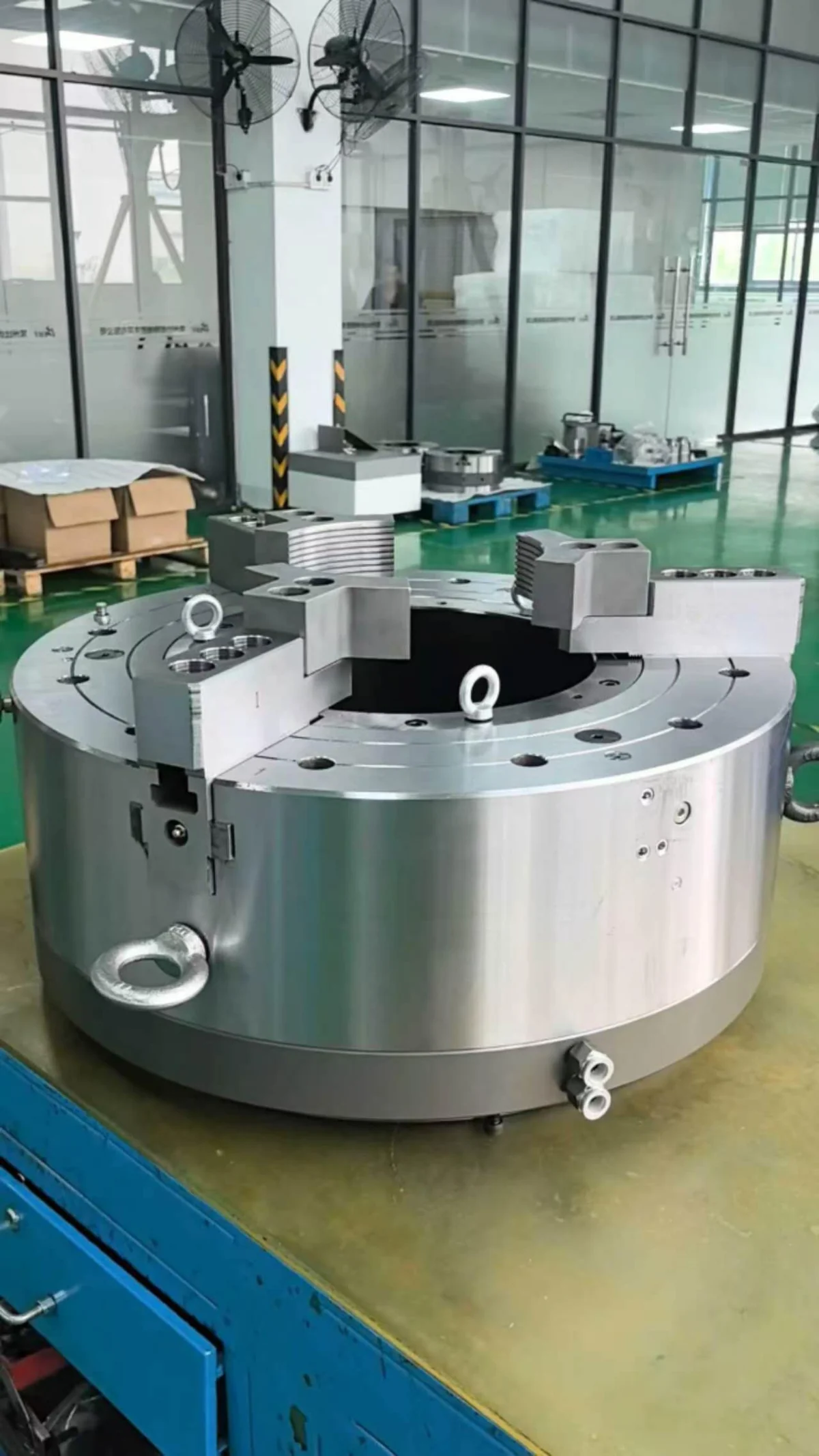
One finished K53 on the bench
Here is one finished K53 on the workbench. You can see its three jaws, central opening and air connections. This is a useful view when checking where a pipe sits and how the chuck connects to the air supply.
The K53 is a front-mounted pneumatic chuck for oil pipe threading, including casing and tubing work. The pipe dimensions and threading operation determine which size and gripping arrangement to use.
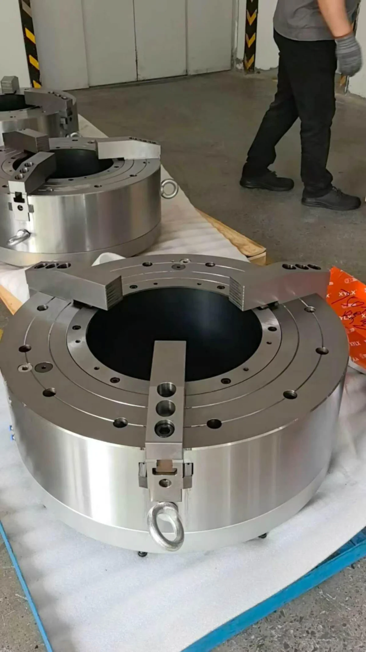
The customer batch together
This photo shows several chucks from the newly finished batch. The front unit sits on protective material, with more completed chucks behind it. These are the actual units produced for the customer.
For a pipe-threading job, start with the pipe diameter, wall thickness and where it will be gripped. Then check how much room the threading tool needs at the pipe end. Choosing only by chuck outside diameter leaves out those details.
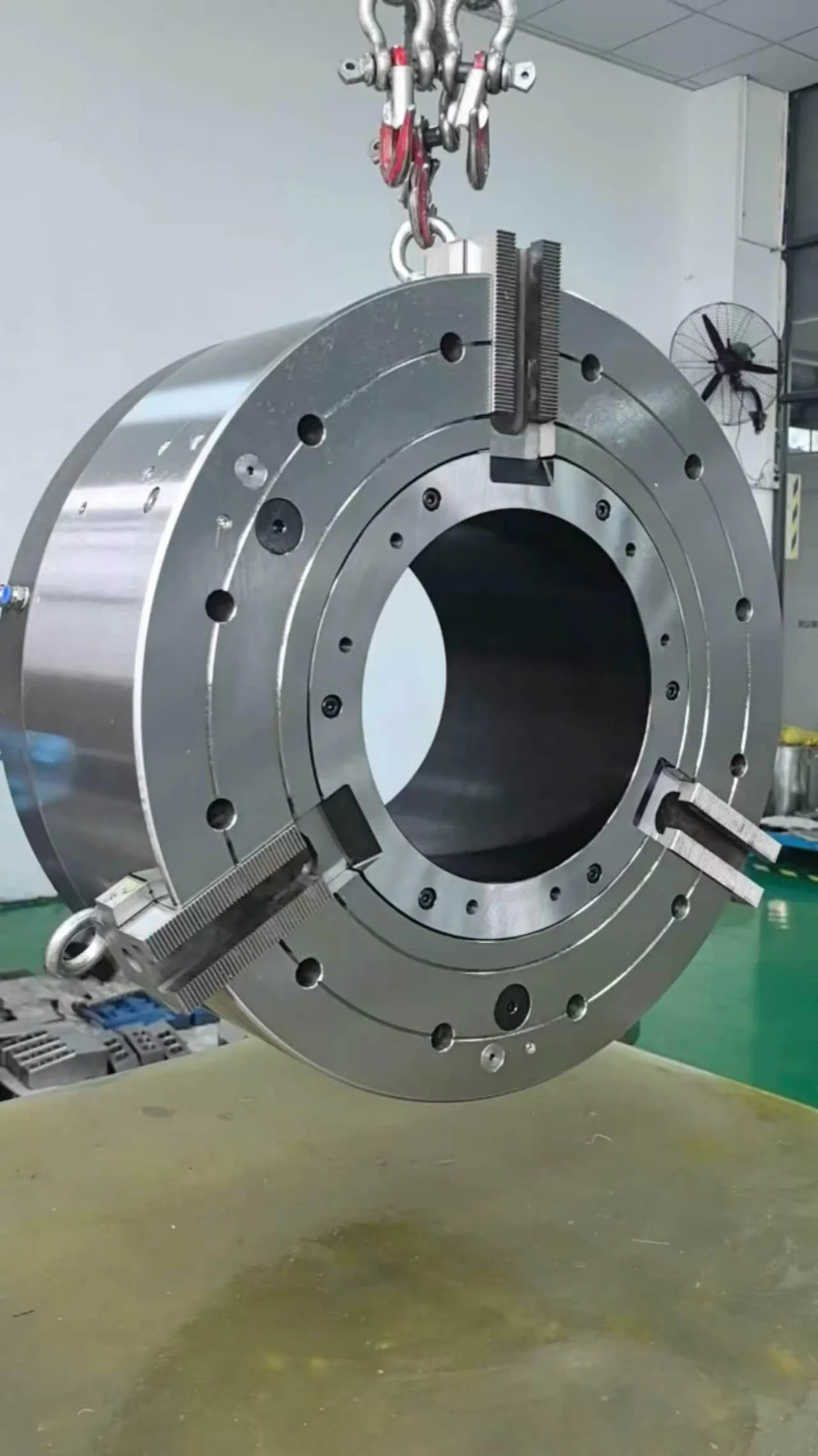
A clear view of the bore and jaws
The upright view gives a clear look through the centre opening and at the three jaws. If the pipe needs to pass through the chuck, check the bore against the pipe size. The jaws also need enough contact with the pipe along the gripping section.
Because the K53 uses a front-mounted pneumatic arrangement, its mounting dimensions and air supply need to suit the machine. For an existing lathe or a new pipe-threading machine, compare the interface drawings before selecting the chuck.
What we need for a similar job
If you need a similar setup, send us the following pipe and machine information:
- Pipe outside diameter, wall thickness, length and material.
- Thread type and the machining operation at the pipe end.
- Machine model, spindle passage and mounting interface drawing.
- Required clamping range, gripping length and jaw travel.
- Available pneumatic pressure and target operating speed.
The K53 product page has dimension drawings and model tables. Compare these with your pipe and machine drawings to narrow down the size and connection you need.
Talk to us about your K53 setup
Send your pipe drawing and machine interface to our team. We can then discuss the K53 size, jaws and air connection for your threading job.