KORRETTO · CLAMPING HEAD SYSTEMS
Blind-Hole Segmented Mandrel System
KORRETTO Blind-Hole Segmented Mandrel System is used for internal clamping of workpieces with blind holes, semi-through holes or internal locating surfaces. The Blind-Hole Segmented Mandrel System uses a segmented clamping bushing to support the inside diameter and pull the workpiece back against the workpiece end-stop during expansion. The hardened steel segments are connected by vulcanized rubber. Because the metal segments are separated, the clamping bushing can expand in parallel and provide more uniform internal contact.
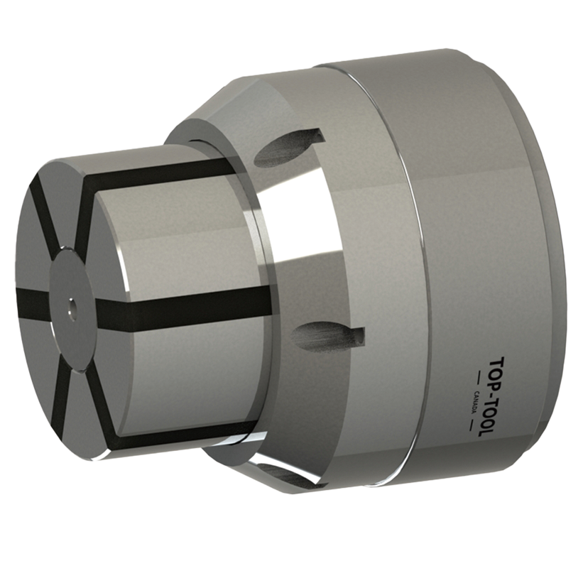
Product Overview
The Blind-Hole Segmented Mandrel System is selected when the part cannot be held effectively from the outside diameter or when outside surfaces must remain open for machining. The internal expansion structure supports the workpiece from the bore, while the pull-back design positions the workpiece against the workpiece end-stop without requiring a draw bolt through the blind bore.
The vulcanized rubber fills the connection between the steel segments, avoiding open metal slots that can readily trap chips. The elastic movement comes from the rubber connection, allowing the steel segments to retain high hardness and wear resistance.
Selection should confirm the bore diameter, bore depth, workpiece tolerance, expansion range, draw force, radial clamping force, maximum speed and whether the application is blind-hole, semi-through-hole or another internal clamping layout.
Key Features
| Feature | Description |
|---|---|
| Internal expansion clamping | Holds the workpiece from the inside diameter. |
| Blind-hole application | Suitable for blind-hole and semi-through-hole parts. |
| Rubber-Flex Segmented Clamping Bushing | Hardened steel segments connected by vulcanized rubber for parallel expansion and distributed internal contact. |
Typical Applications
- Blind-hole workpieces
- Semi-through-hole workpieces
- Parts requiring outside-surface machining
- Bore-located components
- Thin-wall or mark-sensitive parts
- Internal expansion CNC clamping
Technical Data: Blind-Hole Segmented Mandrel System
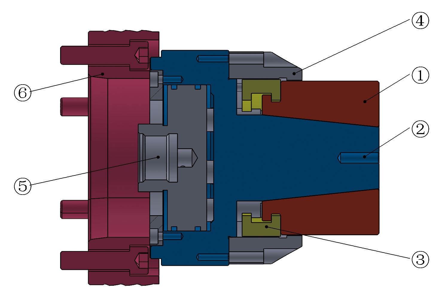
Use the drawing and parameter tables to check chuck structure, stroke, maximum draw force, maximum radial clamping force, clamping range, recommended workpiece tolerance and maximum speed.
| No. | Component | Description |
|---|---|---|
| 1 | Rubber-Flex Segmented Clamping Bushing | Hardened steel segments connected by vulcanized rubber; the separated segments support parallel expansion, reduce chip-trapping openings and provide high wear resistance. |
| 2 | High-Precision Chuck Body | Chuck body made of hardened steel. |
| 3 | Coupling Ring for Quick Change of Segmented Clamping Bushing | Coupling ring for quick change of the segmented clamping bushing. |
| 4 | Workpiece End-stop | End stop for axial positioning of the workpiece. |
| 5 | Draw Tube Connection Mounting Threads | Mounting threads for draw tube connection. |
| 6 | Spindle Flange | Flange of the spindle. |
| Model | Stroke (mm) | Max. Pulling Force (kN) | Max. Radial Clamping Force (kN) | Clamping Range (mm) | Recommended Workpiece Tolerance (mm) | Max. Speed (r/min) |
|---|---|---|---|---|---|---|
| A0 | 1.5+1.5 | 10 | 42 | 8–13 | ±0.2 | 7000 |
| A1 | 1.5+2 | 10 | 42 | 13–19 | ±0.25 | 7000 |
| A2 | 1.5+2 | 10 | 42 | 16–21 | ±0.25 | 7000 |
| 0 | 1.5+2 | 10 | 42 | 20–28 | ±0.25 | 7000 |
| 1 | 1.5+2 | 10 | 42 | 26–38 | ±0.25 | 7000 |
| 2 | 1.5+2 | 20 | 85 | 36–54 | ±0.25 | 7000 |
| 3 | 2+2.5 | 25 | 105 | 50–80 | ±0.35 | 6000 |
| 4 | 2.5+3 | 35 | 150 | 69–100 | ±0.4 | 6000 |
| 5 | 3+3 | 40 | 170 | 100–130 | ±0.5 | 5000 |
| 6 | 3+3 | 40 | 170 | 130–160 | ±0.5 | 4000 |
| 7 | 3+4 | 45 | 190 | 160–190 | ±0.5 | 3200 |
External and Internal Clamping Head Guide
To compare external clamping heads, rubber flex collets, blind-hole internal expansion and through-hole expansion, read the complete clamping head structure and selection guide.
What to Provide Before Quotation
- Blind-bore diameter, tolerance and usable depth
- Workpiece end-stop and required outside machining
- Drawtube interface, operating speed and cutting load
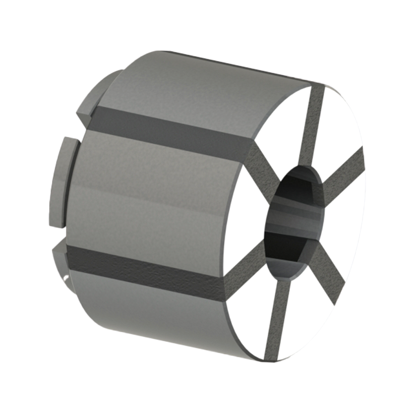
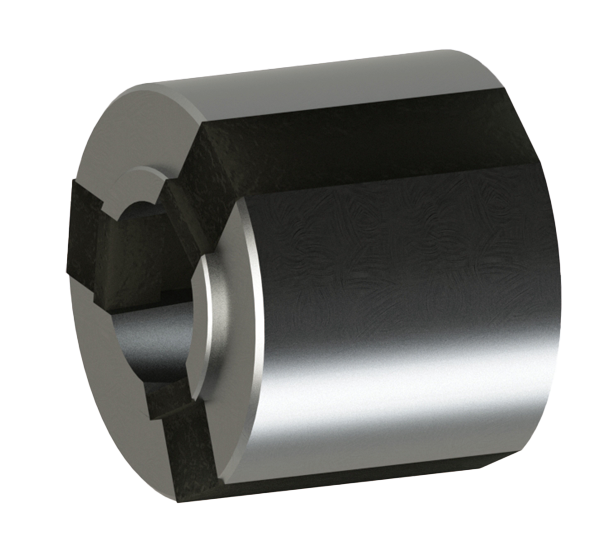
Related Clamping Head Systems
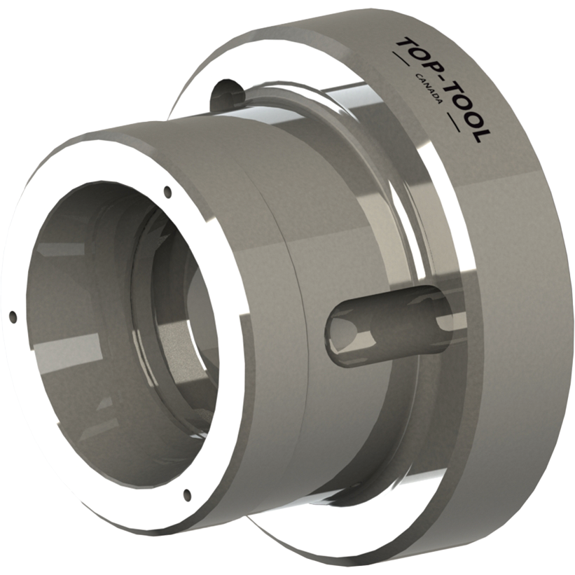
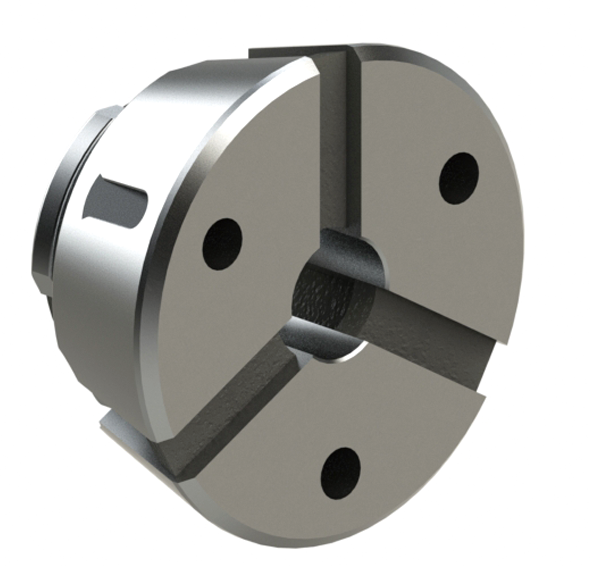
FAQ
What is the Blind-Hole Segmented Mandrel System used for?
It grips workpieces from a blind bore so the outside remains accessible for machining. A rear draw connection and a matched segmented clamping bushing support the internal clamping arrangement.
What is the difference between a Blind-Hole Segmented Mandrel System and a Through-Hole Segmented Mandrel System?
For a Through-Hole Segmented Mandrel System, the drawbar is located at the front of the clamping bushing and covers its end face, helping protect the rubber from chips. In a Blind-Hole Segmented Mandrel System, the drawbar is positioned behind the clamping bushing, which maximizes the available internal expansion depth for blind-hole workpieces.
Is this the same as the Through-Hole Clamping Head Chuck?
No. The Through-Hole Clamping Head Chuck clamps from the outside. This product clamps from the inside by expansion.
What should be checked before selection?
Check bore diameter, bore depth, expansion range, workpiece tolerance, draw force, clamping force, maximum speed and support length.
Can this be used when the outside diameter must be machined?
Yes. Internal expansion clamping is often selected when the outside surface must remain accessible for machining.
What information should I send?
Send the workpiece drawing, bore size, bore depth, tolerance, material, machining process, machine layout and required accuracy.