Ultra-precision diaphragm collet chuck with built-in pneumatic cylinder for precision OD clamping.
Ultra-Precision Diaphragm Collet Chuck with Built-in Pneumatic Cylinder
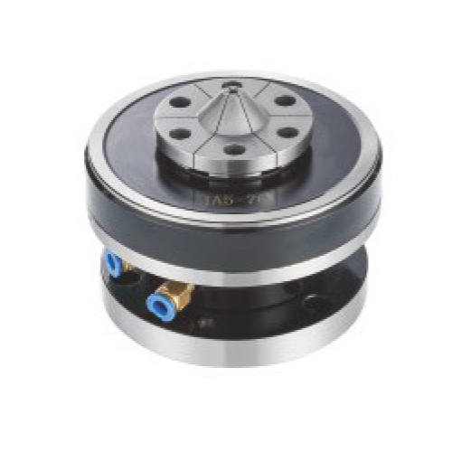
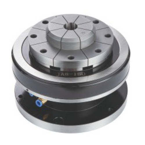
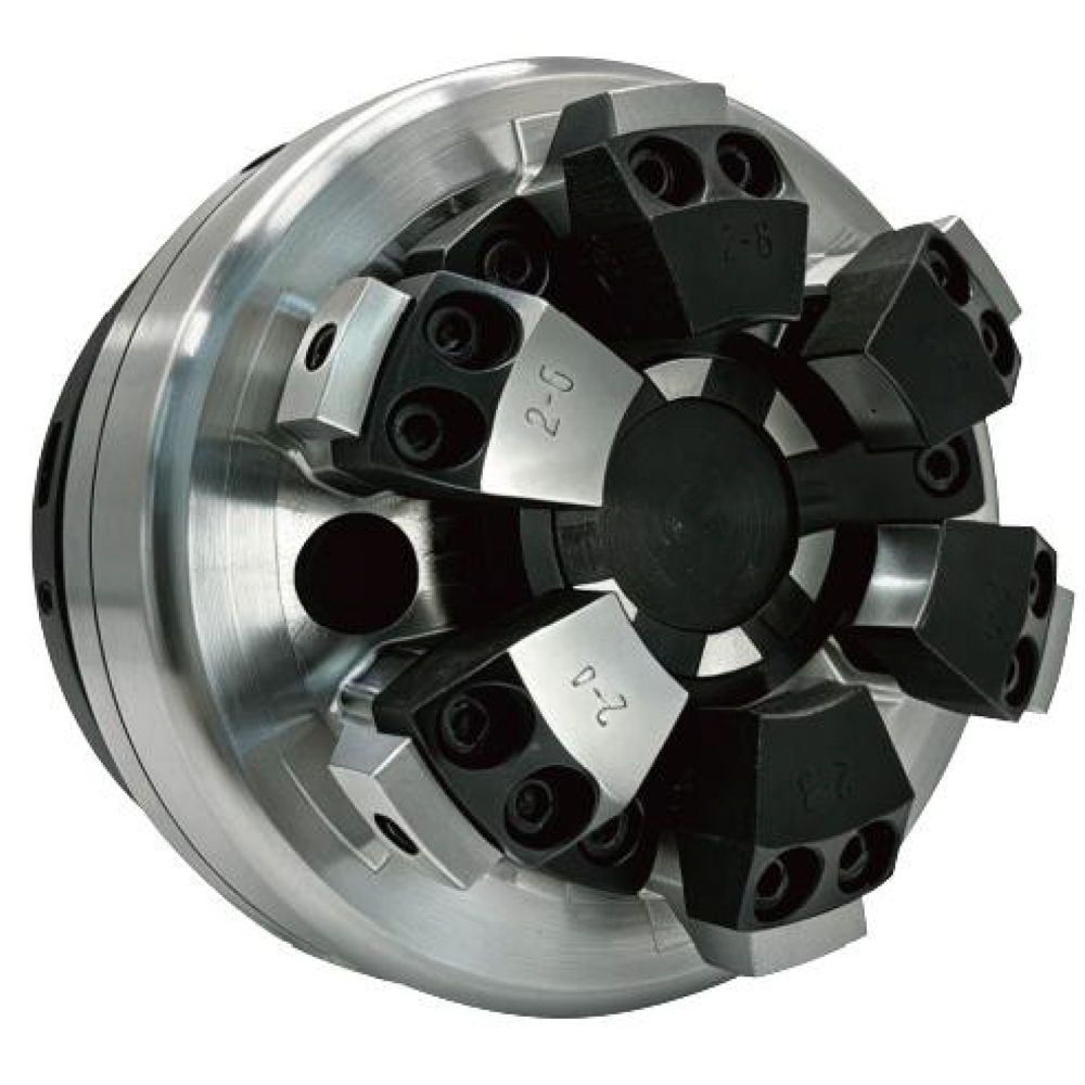
KORRETTO ultra-precision diaphragm collet chuck with built-in pneumatic cylinder is a complete diaphragm chuck unit for precision turning, high-repeat external clamping and low-deformation OD workholding. It works with matching diaphragm collets and uses built-in pneumatic actuation to open and clamp the workpiece. This page covers the complete diaphragm chuck unit, not the diaphragm chuck collection page.
Product Overview
This product is a stationary diaphragm chuck unit with a built-in pneumatic cylinder. It is used with matching diaphragm collets to clamp the workpiece from the outside diameter and is suited to precision OD clamping, thin-wall parts, finishing operations and low-deformation workholding where repeatability matters.
The built-in pneumatic cylinder drives opening and clamping, while the diaphragm and matching collet structure transmit clamping force to the workpiece. Final selection should be confirmed from the workpiece drawing, clamping diameter, gripping length, material, wall thickness, machine interface, air supply and target repeatability.
Key Features
| Feature | Description |
|---|---|
| Complete diaphragm chuck unit | Includes the chuck body and built-in pneumatic cylinder rather than only the replaceable collet element. |
| Built-in pneumatic cylinder | Air pressure drives opening and clamping without requiring a separate external hydraulic station. |
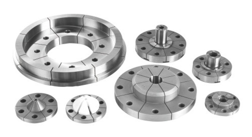
| Matching diaphragm collet system | Works with matching diaphragm collets to achieve stable precision OD clamping. |
| Low-deformation clamping use | Suitable for thin-wall and deformation-prone parts when the contact range and gripping length are matched correctly. |
| Precision production positioning | Used in applications that require controlled clamping marks, stable location and repeatable loading. |
Typical Applications
- Thin-wall rotating parts and rings
- Deformation-prone shafts, flanges and disc parts
- Precision OD turning and finishing
- Repeat clamping stations with tight consistency requirements
- Applications where clamping marks and runout variation must be controlled
- Machine layouts using a built-in pneumatic actuation scheme
Working Principle / Clamping Principle
Air pressure drives the built-in pneumatic cylinder and the diaphragm assembly. The diaphragm deforms elastically and transmits clamping force to the matching diaphragm collet, which then locates and clamps the workpiece from the specified outside diameter.
The final clamping behavior depends on workpiece diameter, gripping length, matching diaphragm collet model, air pressure stability and chuck adjustment. That is why the workpiece drawing, contact range and production condition should be checked together before final model confirmation.
Technical Data for Ultra-Precision Diaphragm Collet Chucks
Use the drawing and parameter table to check installation dimensions, spindle-side interface conditions, working pressure, opening and closing stroke, maximum speed and the matching diaphragm collet specification.
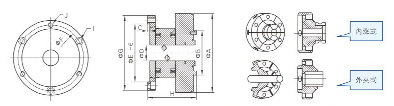
| Model | A | B | C | D | E (H6) | F | G | H | I | J | Max. speed r.p.m | Working pressure kg/cm² | Opening / closing stroke mm | Net weight kg | Compatible jaw / collet |
|---|---|---|---|---|---|---|---|---|---|---|---|---|---|---|---|
| JA4-60 | 100 | 60 | 4 | 10 | 70 | 82 | 97 | 76 | - | 4-M6 countersunk holes | 4000 | 2-7 | 0.1 | 2.8 | JD-60 |
| JA5-70 | 147 | 70 | 4 | 15 | 100 | 115 | 137 | 93 | 3-M8 | 3-M8 countersunk holes | 3200 | 2-7 | 0.3 | 7 | JD-70 |
| JA6-100 | 177 | 100 | 5 | 35 | 130 | 147 | 167 | 107 | 3-M10 | 3-M10 countersunk holes | 2500 | 2-7 | 0.3 | 11.5 | JD-100 |
| JA8-150 | 220 | 150 | 5 | 65 | 180 | 200 | 220 | 124 | 3-M10 | 3-M10 countersunk holes | 2000 | 2-7 | 0.3 | 15 | JD-150 |
The matching diaphragm collet series should be selected together with the chuck unit. Installation hole pattern, matching collet model, air pressure condition and machine interface should all be confirmed before ordering.
Selection and Inquiry Information
- Workpiece drawing with critical dimensions and tolerances
- Clamping diameter and gripping length
- Material, wall thickness and any weak section
- Surface quality and marking limitation
- Machining process, cutting load and target cycle
- Machine interface, mounting space and air supply condition
- Matching diaphragm collet specification or target diameter range
- Repeatability or runout requirement for the process
Related Diaphragm Chuck Pages
- Diaphragm Chucks CollectionOverview of diaphragm chuck structures and related products.
- Fixed Diaphragm ChuckFixed diaphragm chuck unit for repeat precision clamping.
- Rear-Actuated Passive Diaphragm ChuckRear-driven diaphragm chuck structure.
- Collet ChucksBroader collet chuck product range.
- Pneumatic ChucksOther pneumatic workholding structures.
FAQ
What workpieces is this ultra-precision diaphragm collet chuck used for?
It is used for thin-wall rotating parts, deformation-prone workpieces, precision OD finishing parts and components that require repeatable elastic clamping, stable location and controlled clamping marks. Final suitability should still be checked against workpiece geometry, gripping length, cutting load and machine rigidity.
What is the relationship between a diaphragm collet and a diaphragm chuck?
A diaphragm collet is the matching clamping element, while the diaphragm chuck is the complete chuck unit. This product is a complete diaphragm chuck with a built-in pneumatic cylinder and should be selected together with the matching diaphragm collet specification.
How is a pneumatic diaphragm chuck different from a standard pneumatic chuck?
A standard pneumatic chuck can use many different clamping structures. A pneumatic diaphragm chuck specifically uses diaphragm deformation to transfer clamping force, which can be more suitable for thin-wall parts, low-deformation clamping and controlled contact around the workpiece.
How does diaphragm chuck clamping work?
Air pressure drives the built-in pneumatic cylinder, which acts on the diaphragm assembly. The diaphragm deforms elastically and transmits clamping force through the matching diaphragm collet to locate and clamp the workpiece.
Can it be used for thin-wall and deformation-prone parts?
Yes, that is one of the typical applications. It can help reduce local stress concentration compared with more aggressive point-contact clamping, but the final result still depends on wall thickness, gripping length, material and cutting conditions.
What information is needed for quotation?
Please provide the workpiece drawing, clamping diameter, gripping length, material, wall thickness, machine interface, air supply condition, matching diaphragm collet requirement and target repeatability or runout requirement.
Are “thin film chuck” and “diaphragm chuck” the same product?
In some market usage, “thin film chuck” is used loosely for the same diaphragm-based clamping concept. Final confirmation should always be based on the actual diaphragm chuck structure, the matching collet specification and the product drawing.
How should a CNC lathe diaphragm chuck be installed?
Installation should follow the machine interface, mounting dimensions, air connection and product technical documents. Bolt pattern, air supply routing, opening and closing stroke, and matching diaphragm collet setup should all be checked before operation.