JH Collet Chuck in a Motor Rotor Machining Setup
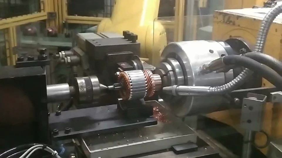
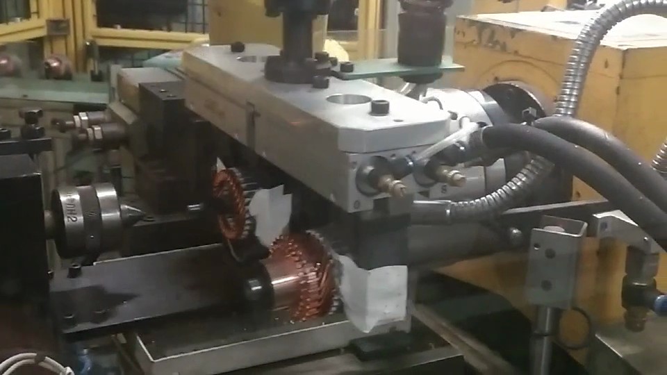
The video shows the workholding arrangement around a motor rotor. The JH rotary collet chuck is on the right, gripping an end section of the shaft. The rotor body remains between the end supports. The view separates the shaft gripping area from the larger rotor body.
How the grip works
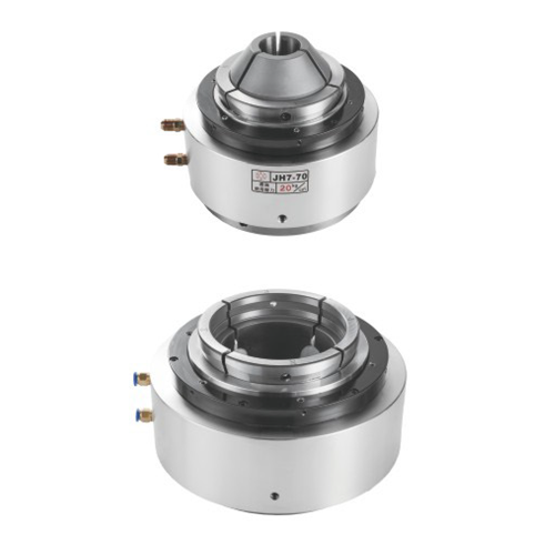
The JA/JH family combines the actuator and rotary gripping unit. JA uses pneumatic actuation. JH uses hydraulic actuation. A matching collet grips the part while the machine drives rotation. Select the drive pressure, collet size and spindle connection as one setup.
The gripping position controls access for a cutting tool or laser head. Long tubes and shafts also need a suitable support and feed arrangement. Set the part projection, support position and working area before fixing the chuck and its mounting unit in place.
What to check in this setup
- Select the collet for the shaft section.
- Check rotational clearance around the rotor body.
- Plan end supports and axial location together.