Front-Mounted Pneumatic Diaphragm Chuck Runout Check
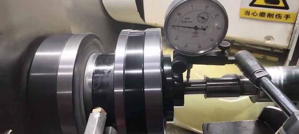
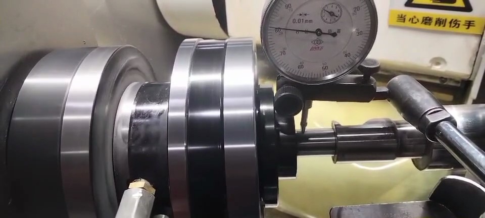
The chuck is mounted at the front of the machine, with a slender part projecting down from the gripping opening. The indicator touches the outside diameter. An air fitting is visible at the side. The view brings the grip, air connection and inspection point together.
How the grip works
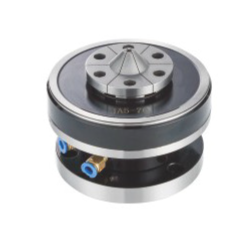
The built-in pneumatic cylinder flexes a metal diaphragm. Its gripping segments move with that small elastic deflection. The grip does not depend on conventional jaws travelling along long slideways. A replaceable diaphragm collet is finished to match the part. External gripping closes onto the outside diameter. Internal gripping expands against the bore.
Choose the gripping direction from the machining datum. Gripping inside a bore leaves the outside diameter accessible. For a slender shaft or thin wall, set the contact length, overhang and clamping force together. After mounting, check the chuck datum first, then the gripped part.
What to check in this setup
- Check the front mounting face and interface.
- Leave room for the side air fitting.
- Place the indicator at the relevant working position.