JA5-70 Diaphragm Chuck in a Grinding Cycle
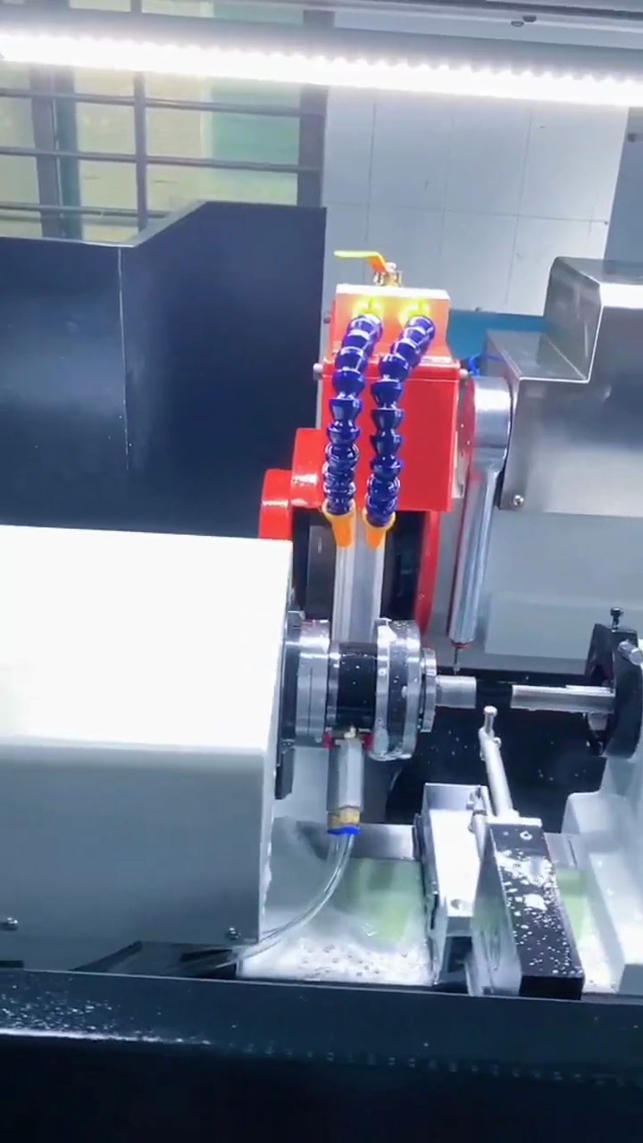
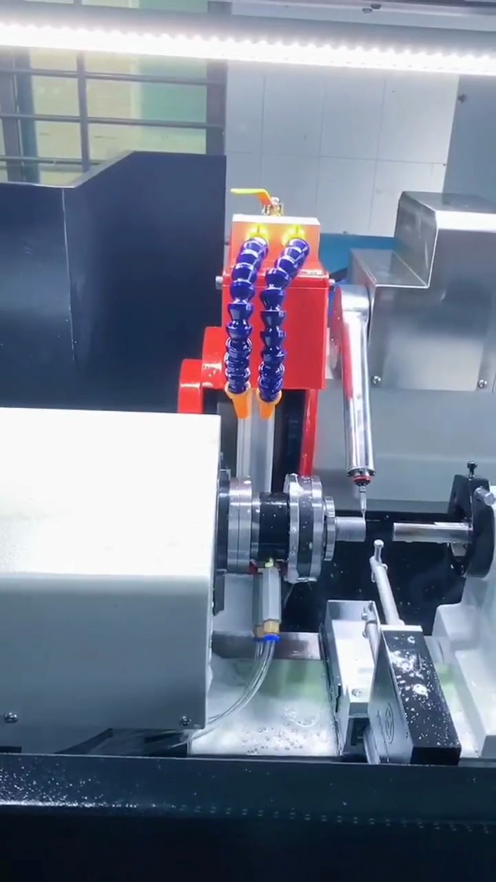
The JA5-70 sits to the left of the grinding wheel, with the part extending into the working area. The portrait view includes the spindle, wheel and coolant lines. It shows where the chuck fits within the grinding station.
How the grip works
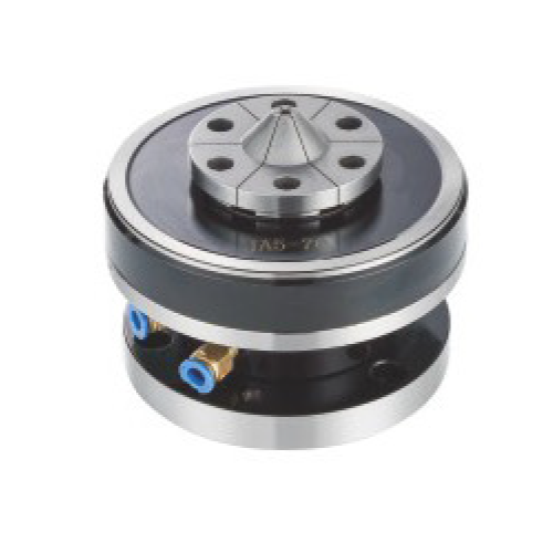
The built-in pneumatic cylinder flexes a metal diaphragm. Its gripping segments move with that small elastic deflection. The grip does not depend on conventional jaws travelling along long slideways. A replaceable diaphragm collet is finished to match the part. External gripping closes onto the outside diameter. Internal gripping expands against the bore.
Choose the gripping direction from the machining datum. Gripping inside a bore leaves the outside diameter accessible. For a slender shaft or thin wall, set the contact length, overhang and clamping force together. After mounting, check the chuck datum first, then the gripped part.
What to check in this setup
- Locate the grinding section relative to the grip.
- Check rigidity at the chosen projection.
- Route air lines outside the wheel travel.