Soft Jaw Bore Diameter and Grip Length Tool: Estimate soft jaw bore diameter, contact arc length, grip length ratio and clamping risk from workpiece diameter, clamping method, jaw count, grip length and machining allowance. The generated sketch is for preliminary sizing reference only, not a final CAD or manufacturing drawing.
Estimate soft jaw bore diameter, contact arc length, grip length ratio and clamping risk from workpiece diameter, clamping method, jaw count, grip length and machining allowance. The generated sketch is for preliminary sizing reference only, not a final CAD or manufacturing drawing.
Analyzing the chuck, standard soft jaw data and workpiece dimensions.
Reading selected chuck model and clamping range
Matching standard soft jaw data
Calculating clamping height, face locating thickness and jaw height
Checking workpiece overhang, chuck diameter and clamping range
Generating sizing sketch and design recommendation
Design recommendation generated
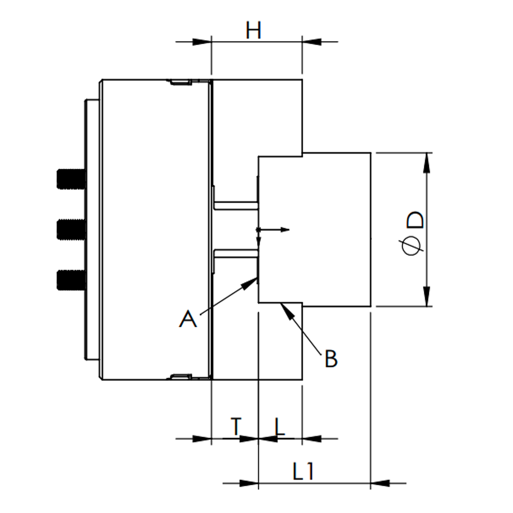
Soft Jaw Sizing Sketch
The following result is generated from the current inputs and recorded standard soft jaw data. It is intended for preliminary sizing reference only.
The soft jaw sketch image is not loaded. Please check /img/tool/soft_jaw_show_1.png and /img/tool/soft_jaw_show_2.png.
The sketch helps visualize soft jaw structure, face locating, clamping surface and key dimensions. It is not a final manufacturing drawing. Final jaw design should be checked against the chuck model, soft jaw blank size, workpiece drawing, clamping position and trial clamping result.
Calculation Results and Data
Soft Jaw Design Recommendation
Soft Jaw Calculation Results
Suggested bore diameter
--
Total jaw height
--
Clamping height
--
Jaw width
--
Face locating thickness
--
Selected Chuck DataSelected Soft Jaw DataFace Locating and Height CheckOverhang and Chuck Matching CheckRisk Notes
Related Workholding Options
How is soft jaw bore size estimated?
OD gripping: suggested bore diameter = target diameter + clearance or interference allowance.
Average arc per jaw = pi x D / jaw count. This is only geometric allocation, not real contact length.
Grip length ratio = planned grip length / D. Small ratios require review for slip, vibration and stability.
Soft jaw forming method reference
The following notes summarize key checks for soft jaw attachment, forming and trial cutting. Actual practice depends on chuck model, jaw blank, machine condition and the relevant chuck manual, so final manufacturing steps still require engineering review.
Jaw attachment and fasteners
The soft jaw position should remain within the chuck's specified effective stroke range. Jaw attaching bolts must be tightened to the specified torque, and screw-in depth must be controlled according to the manual to avoid loose jaws, damaged fasteners or workpiece fly-out risk.
Gripping center height and speed
If the top jaw gripping center height H is higher than the standard soft jaw, the chuck slide and attaching bolts carry higher load, so input force should be reduced. Larger and heavier top jaws also increase centrifugal force, so dynamic gripping force and allowable speed must be checked against cutting force.
OD forming soft jaws
OD forming usually starts with a forming plug or process workpiece with enough thickness and low distortion. Grip it near the center of the jaw stroke, form the soft jaw contact face, then trial cut and check for slip, stable contact and balanced A / B side contact.
ID expanding formation
ID expansion can use a forming ring or expanding process piece. Bore diameter, depth and wall thickness must be checked for distortion. ID expansion often requires more conservative input force, and may require reducing force to a manual-defined percentage of the allowable maximum before trial clamping.
Using a forming jig
When a forming jig is used, pins, bolts or nuts should be distributed evenly on the ring plate, with the gripping position close to the appropriate stroke center. After forming, remove the jig, grip the workpiece and trial cut to confirm accuracy, contact condition and no slipping.
Where this tool is useful
Preliminary soft jaw boring size checks before CNC turning jobs.
Comparing OD gripping and ID expansion soft jaw concepts.
Preparing data for hydraulic chuck, manual chuck or custom fixture inquiries.
Where this tool is not enough for final drawing
Final CAD drawings, jaw strength checks, material deformation and tool interference checks.
Thin-wall, appearance-sensitive, rough OD, interrupted cutting or heavy cutting applications without engineering review.
Any case where zero marks, zero deformation or absolute safety is required.
Parameter Explanation
Target gripping diameter D
Main diameter used for bore size, circumference and ratio calculations.
Clearance or interference allowance
Positive or negative sizing offset. It is not an absolute recommendation.
Grip length L
Axial contact length planned on the soft jaw face.
Soft jaw bore diameter is preliminarily estimated from the target gripping diameter, clamping method and clearance or interference allowance. For OD gripping, the estimate can be workpiece diameter plus allowance. For ID expansion, it can be bore diameter minus allowance. Final sizing still depends on pre-clamping, jaw blanks and trial clamping results.
Why should soft jaws be pre-clamped before boring?
Pre-clamping keeps the jaws close to their real clamping condition while boring, so the finished contact surface is closer to the working deformation state. The pre-clamping method, force and spacer position can affect the contact result.
How should soft jaw grip length be judged?
Grip length can be screened by the ratio between planned grip length and workpiece diameter. A small ratio requires attention to slipping, vibration, marks and stability. A larger ratio still needs checks for tool interference, face locating and jaw stroke.
Are ordinary soft jaws suitable for thin-wall parts?
Thin-wall parts usually need larger contact area, more even clamping and more careful clamping force control. Form jaws, rubber collet chucks, diaphragm chucks or expanding mandrel solutions may be worth evaluating.
How can soft jaw marks be reduced on appearance parts?
Appearance parts can benefit from form jaws, larger contact area, protective pads, rubber collet chucks or dedicated fixtures. Whether marks can be avoided depends on material, surface condition, clamping force and trial results.
How do I choose between ID expansion and OD soft jaw gripping?
If the bore is the main locating datum and bore diameter, depth and wall thickness are stable, ID expansion or expanding mandrel workholding may be considered. If the OD is the main locating and machining datum, OD soft jaw gripping can be evaluated first.
What should be done when rough OD variation is large?
When rough OD variation is large, soft jaw bore size should be checked against the rough stock range and machining allowance. For draft angles, tapers or irregular profiles, ball-joint chucks, floating compensation chucks or dedicated fixtures should be evaluated.
Can the soft jaw sizing sketch be used as a manufacturing drawing?
No. The SVG sketch only helps visualize soft jaw bore size, grip length and contact range. It is not a final manufacturing drawing. Final design should be checked against chuck model, jaw blank size, workpiece drawing and trial clamping.
When should I submit a drawing for engineering confirmation?
Submit a drawing when the part is thin-walled, appearance-sensitive, rough stock, interrupted cutting, heavy cutting, datum-uncertain or requires form jaws. Material, machining process, machine interface and cycle requirements are also helpful.