Clamping Head Chuck Precision Test on a Small-Diameter Workpiece
Testing a small-diameter part
This video shows an accuracy test of our clamping head chuck holding a small-diameter part. A short section projects from the head, and a lever-type test indicator touches its outside surface. As the chuck turns, the indicator shows the runout at that point.
Where the indicator sits
The clip is about 32 seconds long. The holder stays fixed, with the indicator below the part and its slender tip reaching upward to the surface. The tip follows the same section throughout rotation, so you can watch the pointer move.
Watch the precision test on YouTube
Start with the right head bore
For a small part, start with the correct head bore. It needs to fit the gripping diameter and provide enough contact length. Also check the part tolerance, surface finish and axial location. The grip should use the intended contact area rather than just the edge of the bore.
Use the right bore profile for round, square or hexagonal parts. Smooth heads are an option for finished surfaces; grooved heads offer other gripping surfaces. A machinable head lets you prepare a special bore with the matching bore tool.
What to read over one revolution
Fix the indicator holder securely and keep light, steady contact. Turn the part through one revolution and note the highest and lowest readings. The difference is the total indicated runout at that point. Record the measuring position, part projection and indicator graduation as well.
What actually grips the part?
The rubber does not directly grip the part. Hardened steel segments provide the gripping faces. Vulcanized rubber joins those segments so they open and close together, and fills the gaps. Axial movement against the taper in the matching chuck closes the head around the part.
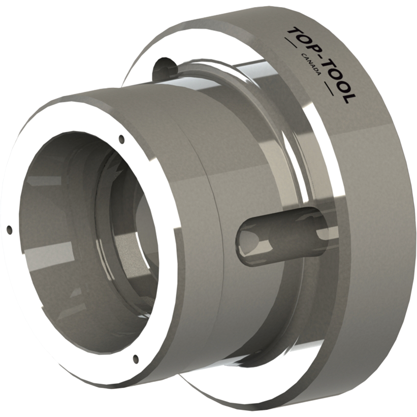
The chuck stays on the machine, while the head is chosen for the part size. For a different component, you can change the matching head without removing the chuck. Label each head with its reference, bore size and contact length so it is easy to find for the next job.
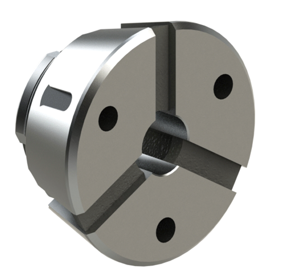
How much to grip and how much to leave out
Plan gripping length and projection together: how much of the part sits inside the head, and how much needs to remain accessible for cutting and measuring? A stop or locating face sets the loading depth. Keep the holder steady and avoid heavy sideways tip pressure on a slender part.
Checking the first part
Before checking the first part, clean the mating and gripping surfaces, fit the correct head and load the part against its reference. Clamp it, then check rotation. Keep the measuring point, loading depth and clamping settings the same for the following parts.
To check repeat clamping, release the same part, take it out and reload it, then compare the readings. Keep the measuring point and clamping settings unchanged. The changing tool removes and installs the head; the bore tool prepares a machinable head. They do different jobs.
Matching chucks, heads and tools
The links below show the matching chuck, heads and tools. Start with the head size, then check the chuck connection and how you will change heads.
- Clamping Head Systems
- Through-Hole Clamping Head Chuck
- Segmented Clamping Head
- Clamping Head Changeover Tool
- Clamping Head Bore Tool
Show us the part you need to hold
Have a similar small-diameter part? Send us the drawing with the gripping diameter, tolerance, gripping length, projection and measuring point. Add the material, machine connection and machining operations so we can discuss the head and locating arrangement in detail.