Our Newly Produced Expanding Mandrel Chuck: Bore-Based Workholding
A newly finished expanding mandrel
We have just finished this expanding mandrel chuck. The two photos show it from the front and side. The slotted sleeve grips inside the workpiece bore; the mandrel and flange support it and provide the mounting connection. That leaves the outside of the part clear for the cutting tool.
What the two photos show
The front view shows the sleeve segments and top face. The side view makes the sleeve length, mandrel projection and flange thickness easier to see. When designing the fixture, we look at bore diameter, usable gripping depth and available mounting space together.
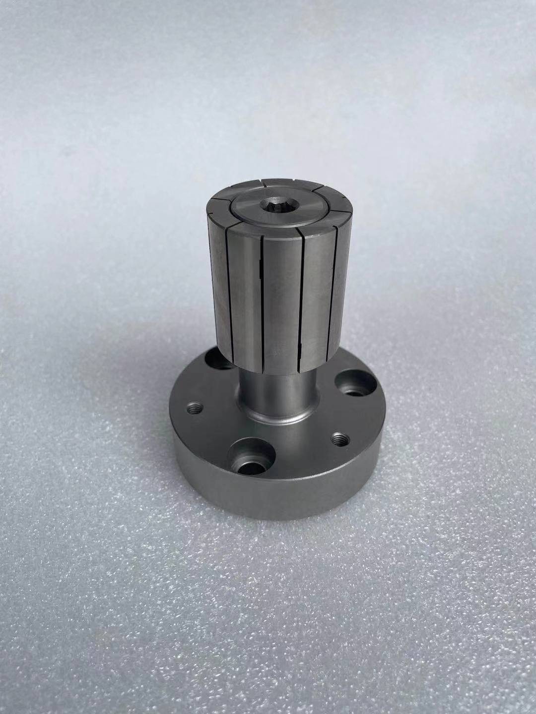
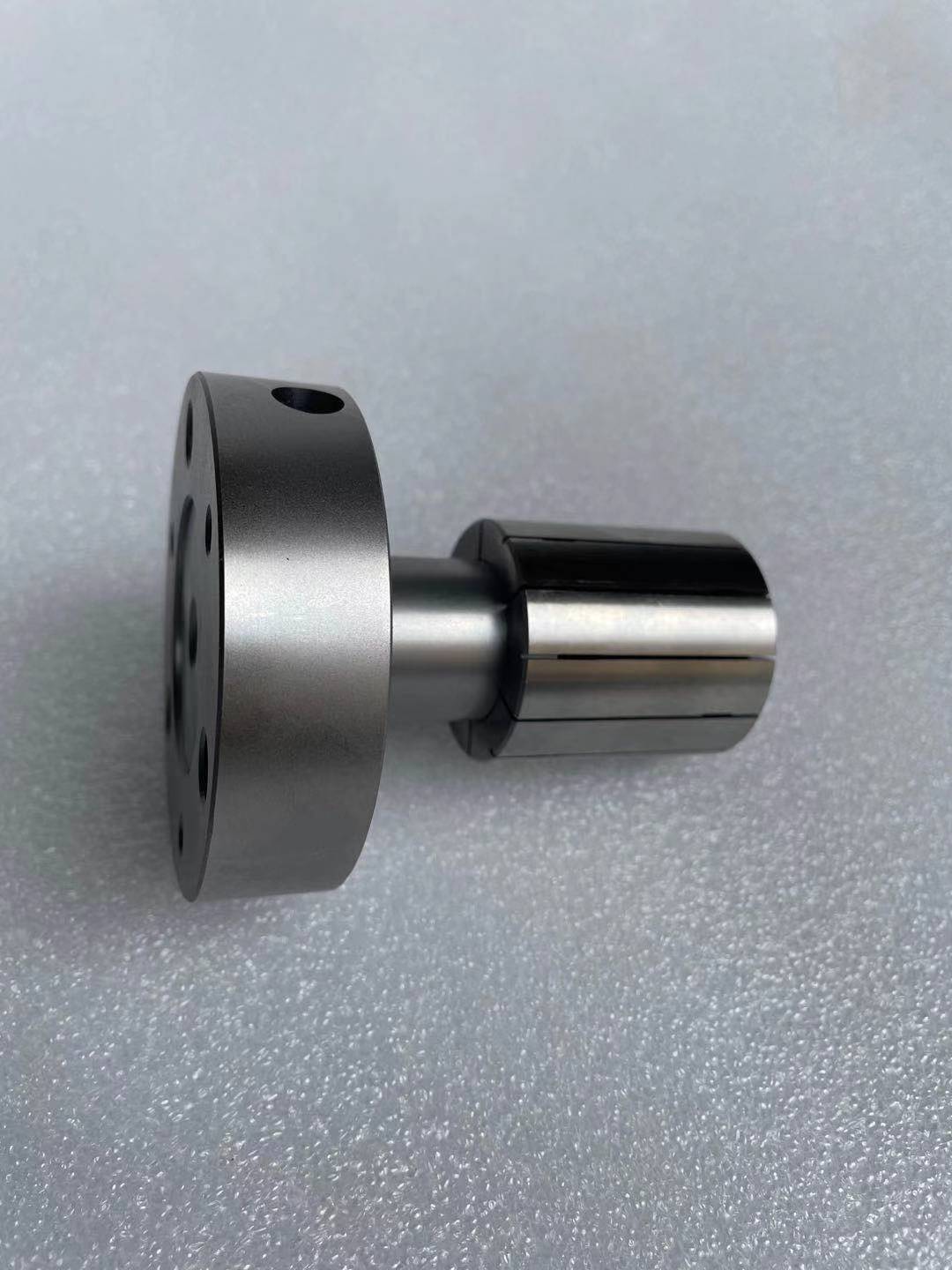
Grip inside and leave the outside clear
An expanding mandrel grips by expanding outward inside a bore. If that bore is the part’s machining reference, you can locate from it before turning the outside or facing the part. With no external jaws in the way, the tool has access to the surfaces you need to machine.
Common jobs include outside turning, facing, external grooves and profiles. Internal gripping is also useful when an already finished outside surface should remain clear of external jaws. Before loading, decide which bore section will grip and which face or shoulder will set the axial position.
Expanding Mandrels & Internal Expansion Clamping Heads
Bore size, gripping length and location
Choose the sleeve for the actual bore diameter and tolerance. Use the available straight section to determine contact length. Show chamfers, relief grooves, steps and blind-hole bottom clearance on the drawing. The full part length is not necessarily the usable gripping length.
The sleeve expands radially; a locating face or stop sets how far the part goes along the mandrel. Identify the locating and machining faces separately and leave tool access. Flange holes, mounting dimensions and mandrel projection also need to suit the machine or fixture.
Consider wall thickness, material and cutting direction. For a thin wall, plan contact area and clamping force together to limit distortion. A part with a long overhang needs planned support. Start with the part and operation before deciding the mandrel layout.
Parts commonly held on a mandrel
Sleeves, bushings, rings, gear blanks and bored flanges are common examples. Once the bore is machined, it can locate the part for the next outside or face operation. For interchangeable sleeves, record bore size, tolerance, contact length and locating face so each sleeve goes with the right job.
Choose the structure for your bore
Through bores, blind holes and shallow bores need different arrangements. A replaceable expansion sleeve and a complete expanding chuck also do different jobs. Use the links below to compare products by bore type and machine mounting.
Expanding Mandrels & Internal Expansion Clamping Heads
Choose by bore type and size.
Blind-Hole Expanding Rubber Collet Chuck
For blind and limited-depth bores.
Through-Hole Rubber Flex Expanding Collet Chuck
View the complete through-bore chuck.
Through-Hole Rubber Flex Expanding Collet
View the replaceable expansion element.
Expanding Mandrel Force Calculator
Estimate force with contact length and wall thickness.
Need a mandrel for your part?
Need a similar mandrel? Send a drawing or 3D model showing bore size and tolerance, depth, material, wall thickness, locating face and machining areas. Add the machine connection, actuation method and loading arrangement so we can discuss the sleeve and mandrel design.