Through-Hole vs Solid Power Chuck: How to Choose for CNC Lathes
A through-hole power chuck and a solid power chuck can both be used for CNC lathe workholding, but they are selected for different workpiece and loading conditions. The main difference is whether the chuck system needs a spindle-through passage for bar stock, tubes or long shafts.
A through-hole power chuck is commonly reviewed when the workpiece or raw material must pass through the spindle. A solid power chuck is commonly reviewed when the workpiece is a short blank, disc, sleeve or individual part that does not need rear feeding. The chuck body, rotary cylinder, drawbar or draw tube, spindle bore, jaw stroke and workpiece loading method should be checked together.
For a broader overview of powered workholding, see What Is a Power Chuck?. For the actuator and drawbar system, see how a hydraulic power chuck works with a rotary cylinder and drawbar.
What is a through-hole power chuck?
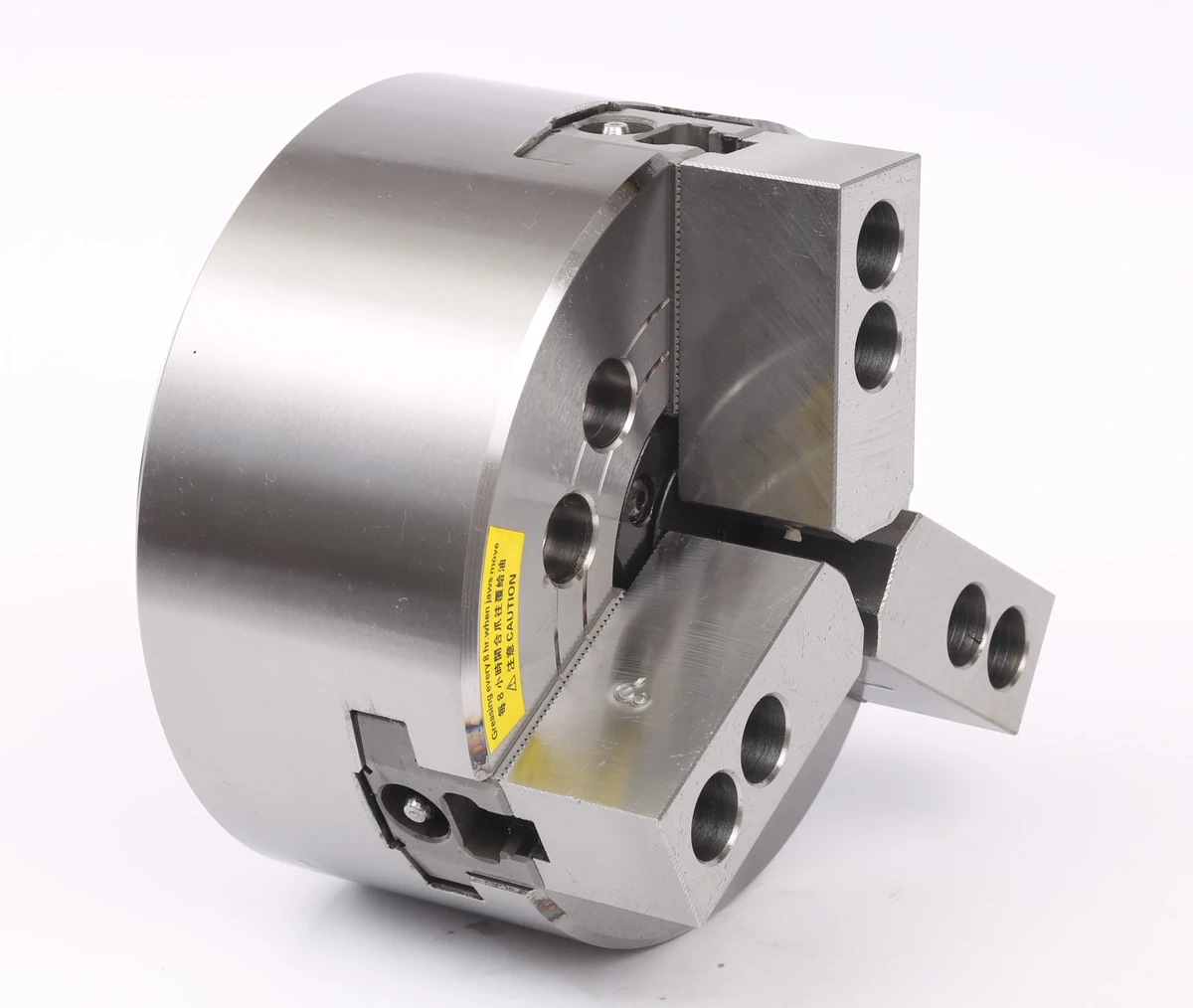
A through-hole power chuck, also called a hollow power chuck or open-center chuck, has a through passage in the chuck body. This allows bar stock, tube stock or long shaft material to pass through the chuck and spindle when the machine and draw tube also support the required passage.
Through-hole power chucks are commonly reviewed for:
- long shafts;
- bar stock;
- tube stock;
- parts loaded from the rear of the spindle;
- spindle-through feeding;
- production where material length extends behind the chuck.
The through-hole function should not be checked from the chuck alone. The spindle bore, draw tube inner diameter, chuck through-hole, workpiece diameter and rear loading method all need to match.
For KORRETTO products, see the 3-jaw through-hole hydraulic power chuck.
What is a solid power chuck?
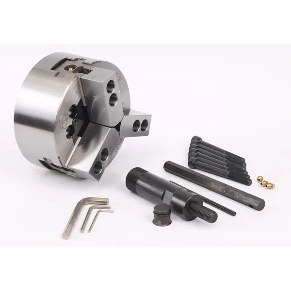
A solid power chuck, also called a closed-center power chuck, does not provide a spindle-through passage. It is commonly reviewed for short blanks, discs, sleeves and individual workpieces where rear feeding is not required.
Solid power chucks are commonly reviewed for:
- short shafts;
- disc-type workpieces;
- sleeve-type workpieces;
- individual blanks;
- manual-to-hydraulic chuck conversion where no through-hole function is needed;
- large-diameter chuck applications where the workpiece is loaded from the front.
A solid chuck may reduce system complexity when a through-hole passage is unnecessary, but the final choice still depends on the machine, workpiece, mounting interface, cylinder and machining process.
For KORRETTO products, see the 3-jaw solid hydraulic power chuck.
Through-hole vs solid power chuck comparison
The difference between through-hole and solid power chucks is not only the chuck opening. It affects the cylinder type, drawbar or draw tube, spindle bore, loading method and overall system layout.
| Selection point | Through-hole power chuck | Solid power chuck |
|---|---|---|
| Main structure | Hollow / open-center chuck body | Solid / closed-center chuck body |
| Material passage | Allows spindle-through passage when the machine and draw tube match | No spindle-through passage |
| Typical workpiece | Long shafts, bar stock, tube stock | Short shafts, discs, sleeves, individual blanks |
| Loading method | Often reviewed for rear loading or bar feeding | Usually front loading or individual part loading |
| Typical cylinder match | Hollow rotary hydraulic cylinder | Solid rotary hydraulic cylinder |
| Key check | Spindle bore, draw tube ID, chuck through-hole and workpiece diameter | Spindle nose, drawbar connection, stroke, force and loading method |
| Common review reason | The workpiece length or feed method requires through-spindle passage | The workpiece does not need rear feeding and a simpler solid system may be practical |
A through-hole chuck is not automatically better. A solid chuck is not automatically cheaper or simpler in every case. The correct selection depends on whether the workpiece, machine and production process actually require through-spindle passage.
How workpiece length and loading method affect the choice
The first question is not the chuck diameter. The first question is how the workpiece enters and leaves the machine.
If the material is long, supplied as bar stock, loaded from the rear of the spindle, or needs to extend through the spindle, a through-hole system is usually reviewed first. The chuck, spindle bore and draw tube must all support the required passage.
If the workpiece is loaded from the front as a short blank, disc, sleeve or single part, a solid chuck may be more practical. The system can focus on spindle interface, clamping force, jaw contact, stroke and cutting load instead of maintaining a through passage.
Typical questions include:
- Does the material need to pass through the spindle?
- Is the part loaded from the front or rear?
- Is the raw material longer than the chuck and spindle nose area?
- Does the process use bar feeding?
- Is the spindle bore large enough?
- Does the draw tube reduce the usable passage?
- Is the part a short blank or disc that does not need rear feeding?
These questions should be answered before comparing chuck price, jaw type or cylinder size.
Matching hollow and solid rotary hydraulic cylinders
A hydraulic power chuck system should be selected as a complete system. A hollow chuck is normally reviewed with a hollow rotary hydraulic cylinder. A solid chuck is normally reviewed with a solid rotary hydraulic cylinder.
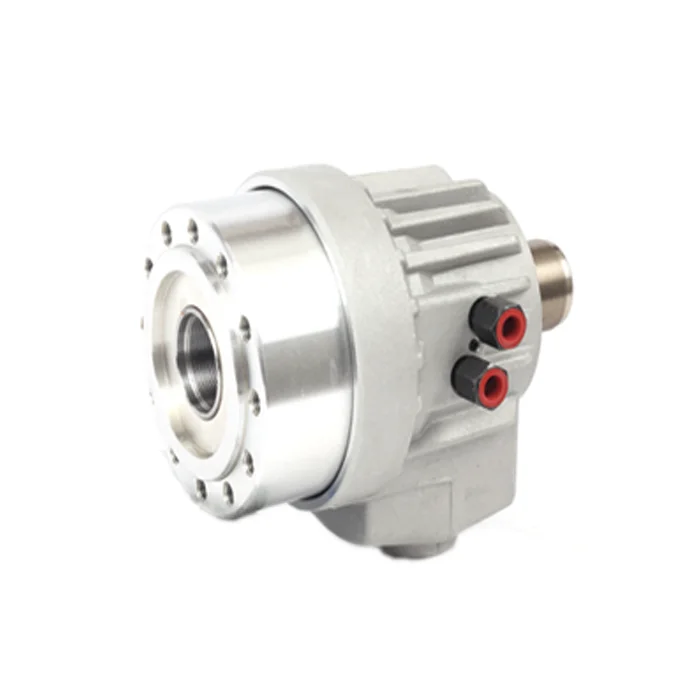
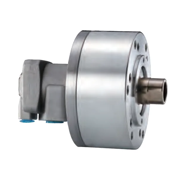
The cylinder is not only an accessory. It defines the available stroke, push / pull force, pressure range, connection method and rotating system requirements. If the cylinder stroke does not match the chuck, the jaws may not open or close correctly. If the drawbar or draw tube is not matched, the chuck may operate outside its intended stroke range.
For cylinder details, see rotary hydraulic cylinder.
Drawbar stroke, jaw stroke and spindle nose checks
Through-hole and solid chuck selection also affects the mechanical interface.
The spindle nose must match the chuck or adapter. The drawbar or draw tube must match the chuck and cylinder connection. The available stroke must be suitable for the chuck mechanism. The jaw stroke must provide enough opening for loading and enough closing range for safe clamping.
Important fields to check include:
- chuck size;
- spindle nose;
- spindle bore;
- through-hole diameter;
- drawbar or draw tube thread;
- plunger stroke or piston stroke;
- jaw stroke;
- maximum pull force or push / pull force;
- maximum clamping force;
- maximum speed;
- clamping range;
- moment of inertia;
- chuck weight;
- matching rotary cylinder;
- hydraulic pressure range.
These fields should be checked by model and catalog table. They should not be estimated from chuck diameter alone.
When to choose a through-hole power chuck
A through-hole power chuck is suitable when the process needs a real passage through the chuck and spindle.
It is commonly reviewed when:
- the workpiece is a long shaft;
- the raw material is bar stock;
- the part is tube stock;
- the machine uses rear loading;
- the process uses bar feeding;
- the workpiece length extends behind the chuck;
- the draw tube and spindle bore must keep a usable inner diameter.
A through-hole chuck may also be reviewed when future production may require bar feeding or longer parts. However, this should be balanced against machine limits, cylinder type, draw tube design and system cost.
For product review, see 3-jaw through-hole hydraulic power chuck.
When to choose a solid power chuck
A solid power chuck is suitable when through-spindle passage is not required.
It is commonly reviewed when:
- the workpiece is a short blank;
- the part is a disc or sleeve;
- the part is loaded from the front;
- the process does not use bar feeding;
- the spindle-through passage is unnecessary;
- a manual chuck is being converted to hydraulic clamping and the workpiece does not require a through hole;
- the chuck is large and the application focuses on front loading and strong support.
A solid chuck can be practical for many short-part turning processes. It may reduce unnecessary hollow-system complexity when the process does not need a passage through the spindle, but the final selection still depends on the machine interface, cylinder, drawbar, jaw stroke and cutting load.
For product review, see 3-jaw solid hydraulic power chuck.
Manual-to-hydraulic conversion notes
When replacing a manual chuck with a hydraulic power chuck, the through-hole question should be answered early.
If the machine and process require long stock or rear feeding, the conversion may need a hollow chuck, hollow cylinder and draw tube system. The spindle bore and draw tube inner diameter become important.
If the process only clamps short blanks or discs from the front, a solid chuck and solid cylinder system may be reviewed. This may reduce system complexity, but it is not a simple one-part replacement. The spindle nose, cylinder mounting, drawbar connection, hydraulic system, safety signal and machine control must still be checked.
A manual-to-hydraulic conversion should not be treated as just changing the chuck body. It is a workholding system change.
Vertical lathe and large chuck considerations
Large-diameter hydraulic chucks and vertical lathe applications are often reviewed as solid structures because the workpiece is usually loaded from the front or from above, and through-spindle bar feeding is not the main requirement.
However, the correct structure still depends on:
- machine type;
- workpiece shape;
- workpiece weight;
- loading direction;
- support surface;
- chuck diameter;
- cylinder or actuation method;
- jaw contact area;
- required speed and cutting load.
Large chucks should also be reviewed for weight, inertia, jaw mass, workpiece mass and safe operating conditions. The decision should be based on the complete machine and workpiece, not only on whether the chuck is hollow or solid.
Selection checklist
Before choosing between a through-hole and solid power chuck, prepare the following information:
- workpiece drawing;
- material and hardness;
- outside diameter and inside diameter;
- workpiece length;
- workpiece weight;
- loading method: front loading, rear loading or bar feeding;
- whether material must pass through the spindle;
- required clamping surface;
- roughing or finishing operation;
- jaw type: hard jaws, soft jaws or custom jaws;
- required jaw opening;
- spindle nose;
- spindle bore;
- drawbar or draw tube thread;
- available drawbar stroke;
- rotary cylinder type: hollow or solid;
- rotary cylinder stroke and force;
- maximum speed requirement;
- machine model;
- automation or robot loading requirement;
- clamp / unclamp confirmation signal.
If you are unsure, start by confirming the workpiece length, loading method and spindle bore. These three items often decide whether a through-hole system is required.
Related KORRETTO pages
FAQ
What is the difference between through-hole and solid power chucks?
A through-hole power chuck has a spindle-through passage for bar stock, tube stock or long shafts when the machine and draw tube also match. A solid power chuck does not provide this passage and is commonly reviewed for short blanks, discs, sleeves and individual workpieces.
When should I choose a through-hole power chuck?
Choose a through-hole power chuck when the workpiece or raw material needs to pass through the spindle, such as long shafts, tubes, bar stock, rear loading or bar feeding applications.
When is a solid power chuck more suitable?
A solid power chuck is commonly suitable when the workpiece is loaded from the front and does not need spindle-through passage. Typical examples include short blanks, disc-type parts, sleeves and individual workpieces.
Can a long shaft use a solid chuck?
A long shaft may require support beyond the chuck, and if the material needs to pass through the spindle, a solid chuck is usually not suitable. The spindle bore, workpiece length and loading method should be reviewed before choosing the chuck type.
Does a through-hole chuck need a hollow rotary cylinder?
A through-hole hydraulic chuck is normally reviewed with a hollow rotary hydraulic cylinder and draw tube so that the system can keep a through passage. The chuck, cylinder, spindle bore and draw tube must be checked together.
Does a solid chuck need a solid rotary cylinder?
A solid hydraulic power chuck is normally reviewed with a solid rotary hydraulic cylinder. The cylinder stroke, force, connection, mounting and speed limits still need to match the chuck and machine.
Is a solid chuck cheaper than a through-hole chuck?
A solid chuck may reduce unnecessary system complexity when through-spindle passage is not required, but it should not be selected only by price. The machine interface, workpiece, loading method, cylinder and process requirements must be checked.
What information is needed to choose between through-hole and solid?
Provide the workpiece drawing, material, outside diameter, inside diameter, length, weight, loading method, spindle nose, spindle bore, drawbar or draw tube data, rotary cylinder information, jaw stroke, clamping surface and maximum speed requirement.