How a Hydraulic Power Chuck Works with a Rotary Cylinder and Drawbar
A hydraulic power chuck does not work alone. It is part of a CNC lathe workholding system that includes the chuck body, jaws, drawbar or draw tube, rotary hydraulic cylinder, hydraulic pressure supply and machine control signal. When these parts are not matched correctly, the chuck may clamp poorly, open only partially, lose usable stroke or fail to fit the machine interface.
The rotary hydraulic cylinder is the actuator. The drawbar or draw tube transfers motion from the cylinder to the chuck. The chuck mechanism converts that motion into jaw movement. For this reason, a hydraulic power chuck should be selected together with the cylinder, drawbar, spindle nose, jaw stroke and workpiece requirements.
For the broader category overview, see What Is a Power Chuck?.
What does a rotary hydraulic cylinder do?
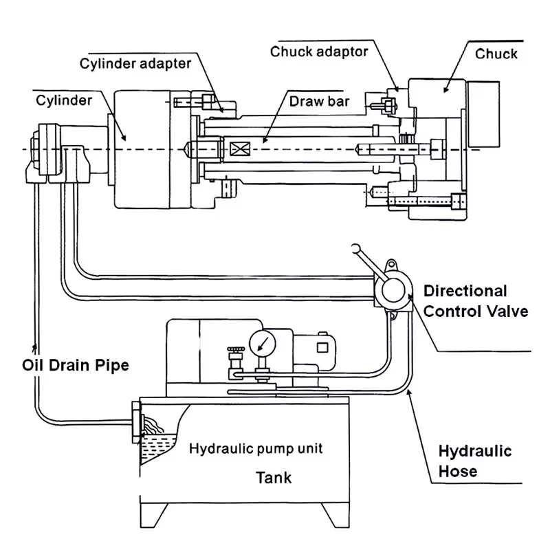
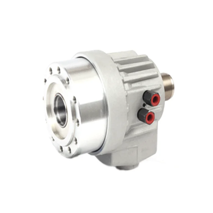
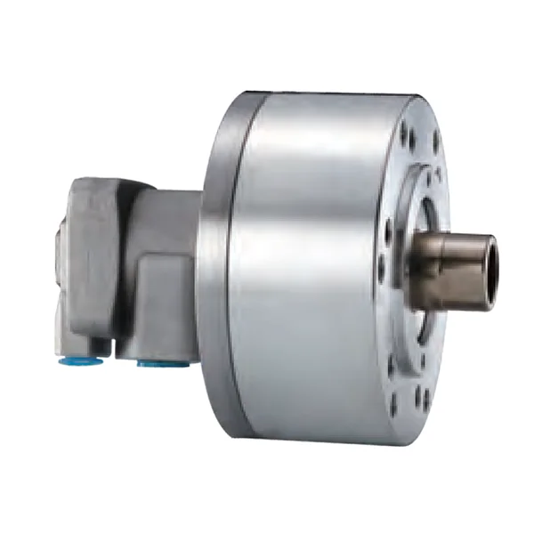
A rotary hydraulic cylinder provides powered actuation while the spindle rotates. It is mounted at the rear side of the spindle system and connects to the chuck through a drawbar or draw tube. When hydraulic pressure moves the cylinder piston, the piston movement pushes or pulls the drawbar. That movement is transferred through the spindle to the chuck mechanism.
The rotary cylinder is not the chuck body. It does not clamp the workpiece directly. Its job is to provide controlled axial movement and force to the chuck system.
A rotary hydraulic cylinder is selected by checking:
- cylinder type: hollow or solid;
- available stroke;
- push / pull force;
- maximum speed;
- pressure range;
- connection to drawbar or draw tube;
- compatibility with the chuck model;
- compatibility with the machine spindle and hydraulic system.
For related KORRETTO products, see rotary hydraulic cylinder.
What is a drawbar or draw tube?
The drawbar, sometimes called a draw tube in hollow systems, is the mechanical link between the rotary cylinder and the chuck. It runs through or along the spindle and transfers the cylinder movement into the chuck.
In a hollow chuck system, a draw tube is often used so the system can keep a through passage for bar stock, tube stock or long shaft material. In a solid chuck system, the connection may not need the same through-hole passage, but the drawbar connection, thread and stroke still need to match the cylinder and chuck.
The drawbar or draw tube must be checked for:
- thread type;
- connection length;
- available stroke;
- strength and rigidity;
- spindle bore clearance;
- connection to the cylinder;
- connection to the chuck mechanism.
If this part is wrong, the chuck may not open fully, may not clamp fully, or may place the jaw movement in the wrong position.
How the cylinder, drawbar and power chuck work together
A hydraulic chuck system works through a sequence of linked movements:
- The machine sends a clamp or unclamp command.
- Hydraulic pressure moves the rotary cylinder piston.
- The piston moves the drawbar or draw tube.
- The drawbar transfers axial movement to the chuck.
- The chuck mechanism converts that movement into jaw opening or closing.
- The jaws clamp or release the workpiece.
- The machine confirms the clamped or unclamped state before the next step.
The system should be reviewed as a complete chain. A correct chuck with the wrong cylinder may not work properly. A correct cylinder with the wrong drawbar length may also cause problems. A correct chuck and cylinder can still fail if the mounting interface, hydraulic pressure, signal logic or jaw setup is wrong.
Main components in the system
| Component | Function | What to check |
|---|---|---|
| Hydraulic power chuck | Clamps the workpiece through jaws | Chuck size, type, spindle nose, jaw stroke and clamping force |
| Rotary hydraulic cylinder | Provides hydraulic actuation while rotating | Hollow / solid type, stroke, force, pressure and maximum speed |
| Drawbar or draw tube | Transfers cylinder movement into the chuck | Thread, length, travel, strength and spindle bore clearance |
| Master jaws | Transfer internal chuck movement to top jaws | Stroke, serration and jaw position |
| Top jaws / soft jaws / hard jaws | Contact the workpiece | Contact area, jaw material, workpiece surface and cutting load |
| Adapter or back plate | Connects chuck to spindle interface | Mounting accuracy and spindle nose compatibility |
| Hydraulic supply and valves | Provide pressure and control direction | Pressure setting, leakage, valve sequence and safety |
| Machine signal | Confirms clamp / unclamp state | Required for CNC cycle and automation review |
This is why selection cannot be based only on chuck diameter. The machine-side actuator and connection parts are equally important.
Hollow chuck with hollow rotary cylinder
A hollow hydraulic power chuck is used when the workpiece, bar stock or tube stock needs to pass through the spindle. In this case, the chuck is usually matched with a hollow rotary hydraulic cylinder and a draw tube. The spindle bore, draw tube inner diameter, chuck through-hole and workpiece size must be checked together.
Hollow systems are commonly reviewed for:
- long shafts;
- bar feeding;
- tube workpieces;
- parts loaded from the rear of the spindle;
- processes that require through-spindle passage.
A hollow chuck is not automatically the correct choice for every job. If the part is short and does not need rear feeding, a solid system may be simpler or more economical.
Solid chuck with solid rotary cylinder
A solid hydraulic power chuck is used when through-spindle passage is not needed. It is commonly reviewed for short shafts, discs, sleeves and individual blanks. It is normally matched with a solid rotary hydraulic cylinder.
Solid systems are commonly reviewed for:
- short workpieces;
- disc-type parts;
- sleeve-type parts;
- manual-to-hydraulic conversion where a through hole is unnecessary;
- large vertical lathe chuck applications.
When a manual chuck is replaced with a hydraulic chuck, the through-hole requirement should be checked first. If the process does not need a spindle-through passage, a solid chuck and solid cylinder system may reduce complexity and cost. Final selection still depends on the machine, workpiece and process.
| Selection point | Hollow chuck + hollow cylinder | Solid chuck + solid cylinder |
|---|---|---|
| Through-spindle passage | Required | Not required |
| Typical workpiece | Long shaft, bar stock, tube stock | Short shaft, disc, sleeve, individual blank |
| Draw connection | Draw tube / hollow connection | Solid drawbar connection |
| Main check | Spindle bore, through-hole, tube clearance | Mounting, stroke, force and cost |
| Common review case | Rear loading and bar feeding | Short parts and no rear feeding |
Drawbar stroke vs jaw stroke
Drawbar stroke and jaw stroke are related, but they are not the same.
Drawbar stroke is the axial movement supplied by the cylinder and transferred through the drawbar or draw tube. Jaw stroke is the opening and closing movement at the jaws. The chuck mechanism converts one movement into the other, so the values are not equal unless the chuck design says so.
Important selection points include:
- cylinder stroke must match chuck requirement;
- drawbar thread and length must be correct;
- jaw stroke must be enough for loading and unloading;
- the jaws must close in the correct clamping range;
- the workpiece must clear the jaws during automation;
- the chuck must not be operated outside its intended stroke.
A common setup problem is that the chuck is installed but the jaws do not open enough, close enough or reach the required gripping range. This should be checked by reviewing the chuck model, cylinder stroke, drawbar length and jaw setup together. The solution should be based on the machine and product documentation, not on generic adjustment advice.
Common setup problems to avoid
A hydraulic chuck system can create problems if the parts are not selected and installed as a system. Common review points include:
- spindle nose does not match the chuck or adapter;
- drawbar thread does not match the chuck or cylinder;
- drawbar length places the chuck outside its working stroke;
- cylinder stroke is not enough for the required jaw movement;
- jaw stroke is enough for clamping but not enough for loading clearance;
- hollow chuck is paired with the wrong hollow cylinder or draw tube;
- solid chuck is selected when through-spindle loading is required;
- clamping force is reviewed without checking jaw contact and cutting load;
- maximum speed is considered without checking chuck, jaws, workpiece and machine limits;
- automation is planned without checking part clearance and clamp confirmation.
This article does not provide repair instructions or machine-specific parameter changes. For installation and retrofit work, the machine builder, hydraulic system supplier and workholding supplier should confirm the details.
What to check before selection
Before selecting a hydraulic power chuck system, prepare the following information:
- workpiece drawing;
- material and hardness;
- outside diameter and inside diameter;
- workpiece length and weight;
- clamping surface;
- datum or locating face;
- roughing or finishing operation;
- required jaw opening;
- chuck type: hollow or solid;
- cylinder type: hollow or solid;
- spindle nose;
- spindle bore;
- drawbar or draw tube thread;
- available drawbar stroke;
- rotary cylinder stroke and force;
- hydraulic pressure range;
- maximum speed requirement;
- machine model;
- automation or robot loading requirement;
- clamp / unclamp confirmation signal.
For standard product families, see KORRETTO hydraulic chucks. For special clamping structures, see application-specific power chucks.
Related KORRETTO pages
FAQ
What does a rotary hydraulic cylinder do?
A rotary hydraulic cylinder provides hydraulic actuation while the spindle rotates. It moves the drawbar or draw tube, and that movement is transferred to the chuck mechanism to open or close the jaws.
What is the role of the drawbar in a hydraulic power chuck system?
The drawbar or draw tube connects the rotary cylinder to the chuck. It transfers the cylinder movement through the spindle into the chuck mechanism. Its thread, length and available stroke must match the chuck and cylinder.
What is the difference between drawbar stroke and jaw stroke?
Drawbar stroke is the axial movement supplied by the cylinder and drawbar. Jaw stroke is the jaw opening and closing movement at the chuck. The chuck mechanism converts one movement into the other, so the two values are not the same.
Why does the chuck not open fully?
A chuck may not open fully if the cylinder stroke, drawbar length, drawbar thread, jaw setup or chuck model is not matched correctly. The cause should be checked from the complete machine and chuck system rather than adjusted by guesswork.
Can a manual chuck be converted to hydraulic clamping?
It may be possible on some machines, but the review must include spindle nose, cylinder mounting, drawbar or draw tube, hydraulic supply, safety signal, chuck type and workpiece requirement. It should not be treated as a simple chuck replacement.
How do I match a hydraulic chuck with a rotary cylinder?
Check whether the chuck is hollow or solid, then match the cylinder type, stroke, push / pull force, connection thread, maximum speed, pressure range and mounting interface. The chuck catalog and machine conditions should be reviewed together.
What is the difference between hollow and solid rotary hydraulic cylinders?
A hollow rotary hydraulic cylinder supports through-spindle passage and is usually matched with a hollow chuck. A solid rotary hydraulic cylinder is used when through-spindle passage is not needed and is usually matched with a solid chuck.
What information is needed for a hydraulic chuck system review?
Provide the workpiece drawing, material, chuck type, machine model, spindle nose, spindle bore, drawbar or draw tube data, rotary cylinder information, required jaw opening, clamping surface, maximum speed and automation requirement.