Four-jaw through-hole hydraulic chuck for square parts and four-point CNC lathe clamping.
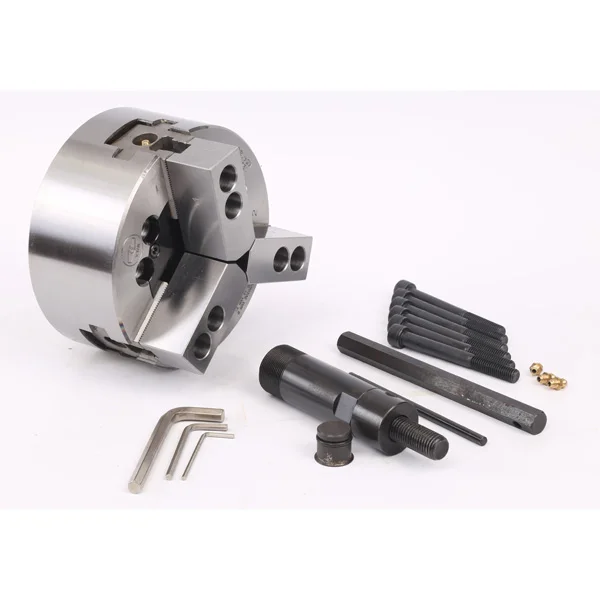
4-Jaw Hollow Hydraulic Power Chuck
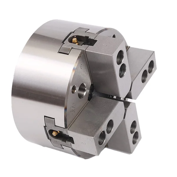
KORRETTO 4-jaw hollow hydraulic chuck provides synchronized four-jaw hydraulic clamping for square parts, four-sided workpieces and applications where four-point contact is preferred. The hollow structure supports through-spindle passage when tube, bar or long workpiece clearance is required. Selection should check workpiece shape, through-hole size, spindle nose, drawbar stroke, cylinder thrust, jaw stroke and cutting load.
Product Overview
The 4-jaw hollow hydraulic chuck is used when the workpiece benefits from four-point support rather than standard three-jaw clamping. It can be used for square or four-sided parts and selected round parts where contact distribution is important.
This page only covers the 4-jaw hollow hydraulic chuck. No confirmed 4-jaw solid hydraulic chuck data is included in this page.
Key Features
| Feature | Description |
|---|---|
| 4-jaw synchronized clamping | Provides four-point contact for square or four-sided workpieces. |
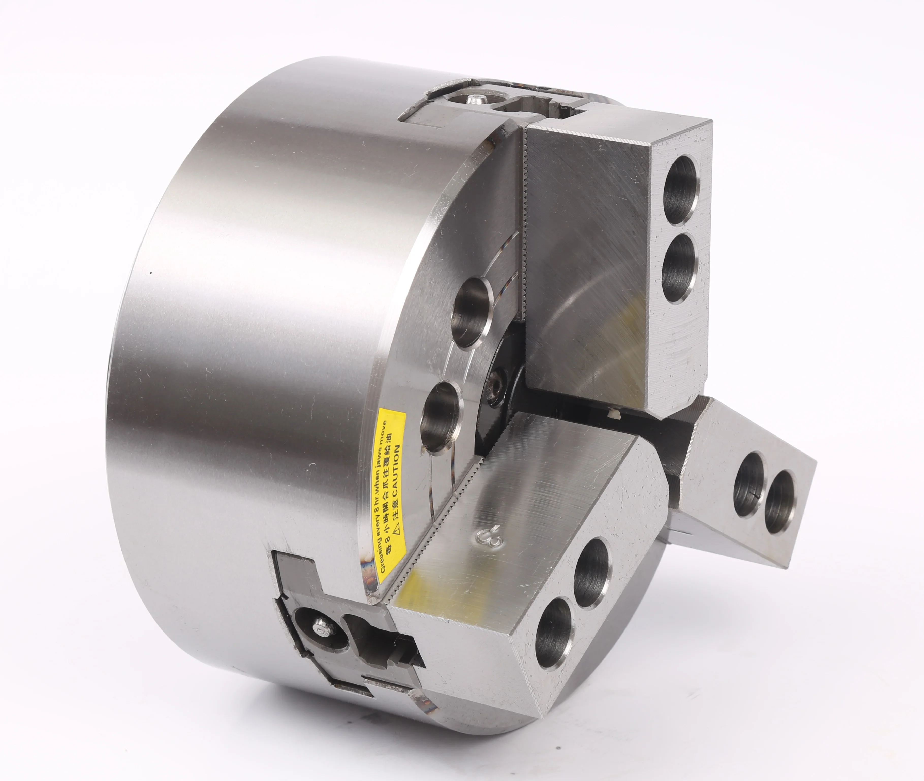
| Hollow structure | Supports through-spindle passage for suitable bar, tube or long parts. |
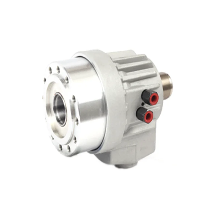
| Hydraulic actuation | Works with compatible rotary hydraulic cylinder and drawbar. |
| CNC production use | Suitable for repeat clamping and stable production cycles. |
| Workpiece-specific jaw setup | Jaw selection should follow the workpiece shape and cutting conditions. |
Typical Applications
- Square parts
- Four-sided workpieces
- Tube or bar parts requiring through-hole clearance
- CNC lathe batch turning
- Workpieces requiring four-point support
Technical Data and Dimensions
Use the drawing and parameter table to check chuck size, through-hole diameter, mounting dimensions, jaw stroke, speed, clamping force and compatible cylinder conditions.
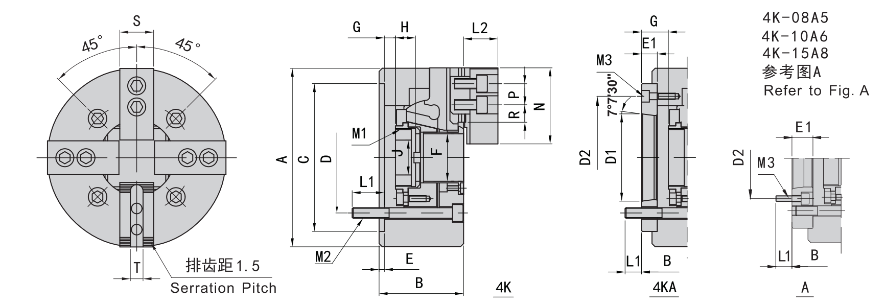
Use this drawing to confirm main dimensions, through-hole size and mounting details.
| Model | Spindle Nose | A | B | C (H6) | D | D1 | D2 | E | E1 | F | G max | G min | H | J |
|---|---|---|---|---|---|---|---|---|---|---|---|---|---|---|
| 4K-04 | 110 | 59 | 85 | 70.6 | 4 | 26 | 3.5 | -6.5 | 17.5 | 12 | ||||
| 4K-05 | A4 | 135 | 60 / 71 | 110 | 82.6 | 63.51 | 96 | 4 | 15 | 45 | 26 | -1 / 14 | 20 | 12 |
| 4K-06 | A5 | 169 | 81 / 91 | 140 | 104.8 | 82.56 | 116 | 5 | 23 | 1 | 16 | -9 / 6 | 19 | 20 |
| 4K-08 | A5 | 210 | 91 / 109 | 170 | 133.4 | 82.56 | 104.8 | 5 | 23 | 52 | 37.5 | -1.5 / 21.5 | 20.5 | 30 |
| 4K-08 | A6 | 210 | 91 / 103 | 170 | 133.4 | 106.38 | 150 | 5 | 17 | 52 | 31.5 | -1.5 / 15.5 | 20.5 | 30 |
| 4K-10 | A6 | 254 | 100 / 120 | 220 | 171.4 | 106.38 | 133.4 | 5 | 25 | 75 | 33.5 | -10.5 / 14.5 | 25 | 45 |
| 4K-10 | A8 | 254 | 100 / 113 | 220 | 171.4 | 139.72 | 190 | 5 | 18 | 75 | 26.5 | -10.5 / 7.5 | 25 | 45 |
| 4K-12 | A8 | 304 | 110 / 122 | 220 | 171.4 | 139.72 | 190 | 6 | 18 | 91 | 26 | -15 / 3 | 28 | 50 |
| 4K-15 | A8 | 381 | 133 / 160 | 300 | 235 | 171.4 | 171.4 | 6 | 33 | 120 | 44 | -12 / 21 | 39 | 60 |
| 4K-15 | A11 | 381 | 133 / 149 | 300 | 235 | 196.87 | 260 | 6 | 22 | 120 | 33 | -12 / 10 | 39 | 60 |
| 4K-18 | A11 | 450 | 133 / 149 | 300 | 235 | 196.87 | 260 | 6 | 22 | 120 | 33 | -12 / 10 | 39 | 60 |
| Model | Spindle Nose | Plunger Stroke (mm) | Jaw Stroke (Diameter, mm) | Max. Pull kN (kgf) | Max. Clamping kN (kgf) | Max. Speed (r/min) | Clamping Range (mm) | Moment of Inertia (kg·m²) | Weight (kg) | Matching Cylinder | Max. Pressure MPa (kgf/cm²) |
|---|---|---|---|---|---|---|---|---|---|---|---|
| 4K-04 | 10 | 5.4 | 13.7(1400) | 28.4(2900) | 8000 | 7-110 | 0.01 | 4 | 428 | 2.1(21) | |
| 4K-05 | A4 | 10 | 5.4 | 17.1(1750) | 35.8(3650) | 7000 | 12-135 | 0.02 | 6.7 / 7.5 | 536 | 2.6(26) |
| 4K-06 | A5 | 12 | 5.5 | 21.5(2200) | 56.8(5800) | 6000 | 15-168 | 0.06 | 11.9 / 13.7 | 646 | 2.5(25) |
| 4K-08 | A5 | 16 | 7.4 | 34.3(3500) | 85.8(8750) | 5000 | 13-210 | 0.18 | 22.5 / 25.4 | 852 | 2.8(28) |
| 4K-08 | A6 | 16 | 7.4 | 34.3(3500) | 85.8(8750) | 5000 | 13-210 | 0.18 | 22.5 / 23.6 | 852 | 2.8(28) |
| 4K-10 | A6 | 19 | 8.8 | 42.6(4380) | 110.7(11300) | 4200 | 31-254 | 0.33 | 34.5 / 41.65 | 1075 | 2.6(26) |
| 4K-10 | A8 | 19 | 8.8 | 42.6(4380) | 110.7(11300) | 4200 | 31-254 | 0.33 | 34.5 / 40 | 1075 | 2.6(26) |
| 4K-12 | A8 | 23 | 10.6 | 54.9(5600) | 143.6(14650) | 3300 | 34-304 | 0.77 | 56.6 / 59.5 | 1291 | 2.6(26) |
| 4K-15 | A8 | 23 | 10.6 | 71(7250) | 179.8(18350) | 2500 | 50-381 | 2.47 | 120 / 134 | 1512 | 2.4(24) |
| 4K-15 | A11 | 23 | 10.6 | 71(7250) | 179.8(18350) | 2500 | 50-381 | 2.39 | 120 / 127 | 1512 | 2.4(24) |
| 4K-18 | A11 | 23 | 10.6 | 71(7250) | 179.8(18350) | 2000 | 50-450 | 4.78 | 164 / 178 | 1512 | 2.4(24) |
Related Hydraulic Chuck Pages
FAQ
What is a 4-jaw hydraulic power chuck used for?
It is used for CNC lathe clamping of square, four-sided or special workpieces that benefit from four-point support and may require through-spindle clearance.
How is this model different from a 3-jaw hydraulic chuck?
A 3-jaw hydraulic chuck is usually preferred for round and standard rotational parts. A 4-jaw hydraulic power chuck is selected when four-point contact or better support for square and four-sided workpieces is needed.
Is this the same as a 4-jaw independent chuck?
No. This is a hydraulic power chuck with synchronized jaw movement. A 4-jaw independent chuck is manually adjusted jaw by jaw.
What machine or spindle interface should be confirmed?
Check spindle nose, chuck mounting dimensions, drawbar thread, drawbar stroke, matching rotary hydraulic cylinder and machine model before selection.
How should the through-hole structure be selected?
Choose the through-hole hydraulic chuck when the workpiece, tube or bar material must pass through the spindle. The chuck through-hole, spindle bore and drawbar layout should be checked together.
How are clamping force, speed and pressure selected?
They should be selected according to workpiece shape, contact area, material, cutting load, rotary cylinder thrust and the machine speed range.
Can it be used for automated production?
Yes. Hydraulic clamping and release can be used for repeat production and automated loading when the workpiece shape, jaw setup and machine safety conditions are suitable.
What information is needed for quotation?
Provide the workpiece drawing, workpiece shape, machine model, spindle nose, spindle through-hole, drawbar data, rotary cylinder model, chuck size and required clamping range.