Power Chuck Replacement Guide
Power Chuck Mounting Interface and Drawbar Data: What to Check Before Replacement
Replacing a CNC lathe power chuck is not only a matter of chuck diameter. Before a replacement chuck is confirmed, the mounting interface, spindle nose, adapter plate, drawbar or draw tube data, rotary cylinder stroke and rear clearance must be checked as one system.
A chuck model may look correct by size or jaw count, but it may still fail to fit the machine if the spindle interface, bolt pattern, drawbar thread, actuator stroke, through-hole clearance or adapter plate does not match. For this reason, replacement projects should start from machine and interface data, not only from the visible chuck body.
Why Replacement Is Not Only About Chuck Size
Chuck diameter is only one part of replacement selection. A CNC lathe power chuck also needs to match the spindle nose, mounting face, actuator system and workpiece loading condition.
Two chucks with similar outside diameter may have different mounting dimensions, different drawbar connections, different through-hole clearance or different required rotary cylinder stroke. The replacement should be checked against the chuck drawing, machine spindle interface and existing cylinder data.
Spindle Nose and Mounting Interface
The spindle nose defines how the chuck or adapter plate connects to the lathe spindle. Common checks include the spindle nose type, mounting diameter, bolt pattern, locating face and available installation space.
The chuck drawing should be compared with the machine spindle data before ordering. If the chuck does not mount directly to the spindle, an adapter plate or back plate may be required.
What Spindle Nose Data Tells You
Spindle nose data helps confirm the mechanical connection between the machine and the chuck. It does not confirm the full replacement by itself, but it is one of the first items to check.
For replacement work, record the machine model, existing chuck model, spindle nose designation, mounting face dimensions and any adapter plate currently used on the machine.
Why Mounting Dimensions Must Be Checked From the Drawing
Do not rely only on the product name or chuck size. The drawing should be used to check mounting pilot diameter, bolt circle, bolt size, center hole, rear side clearance and the front height of the chuck.
If any of these items differs from the machine or adapter plate, the chuck may require additional machining, a new adapter plate or a different model.
Adapter Plate / Back Plate Check
An adapter plate, sometimes called a back plate, connects the chuck to the machine spindle when the chuck body and spindle nose do not directly match.
The adapter has two sides. One side must match the spindle nose. The other side must match the chuck mounting face. Both sides should be checked before replacement.
Chuck Side and Spindle Side of the Adapter
The chuck side should match the rear mounting pattern of the selected power chuck. The spindle side should match the machine spindle nose. The adapter must also provide the correct locating fit and enough strength for the intended machining operation.
Adapter plate design is machine-specific and should be checked by drawing. This article does not provide adapter machining dimensions.
When an Adapter Plate May Be Required
An adapter plate may be required when the existing machine spindle does not directly match the selected chuck, when replacing a different brand or series, or when the machine uses a custom interface.
In this case, the replacement review should include the spindle side drawing, chuck side drawing and available rear space.
Drawbar or Draw Tube Data
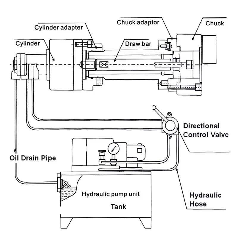
A hydraulic power chuck is usually connected to a rotary cylinder through a drawbar or draw tube. The cylinder movement is transferred through this connection to operate the chuck.
For replacement, the drawbar or draw tube data is as important as the chuck mounting data. The thread, length, stroke, rear connection and through-hole clearance must be checked together with the chuck and cylinder.
Drawbar Thread and Connection Type
The drawbar thread or connection type must match the chuck and actuator system. A mismatch can prevent correct assembly or prevent the chuck from reaching the required open and closed positions.
Final thread and connection details should always be checked from drawings or measured from the existing machine. Do not assume compatibility from chuck size alone.
Drawbar Length and Rear Clearance
Drawbar length affects how the rotary cylinder connects to the chuck mechanism. Rear clearance affects whether the drawbar, cylinder and spindle rear layout can be assembled without interference.
This is especially important when changing from one chuck series to another, replacing an old chuck, or changing between through-hole and solid-center configurations.
Drawbar Stroke vs Jaw Movement
Drawbar stroke is actuator-side movement. Jaw movement is the result at the chuck front after the chuck mechanism converts that movement.
These values are related, but they are not the same. The chuck, cylinder and drawbar should be checked as a system. For more detail, see the article on power chuck jaw stroke and clamping range.
Rotary Cylinder and Actuator Stroke Matching
The rotary hydraulic cylinder supplies the force and stroke required to open and close the chuck. When a power chuck is replaced, the cylinder type and stroke must be checked with the chuck requirement.
A hollow rotary cylinder is usually used with through-hole chuck layouts where bar, tube or long workpiece clearance is required. A solid rotary cylinder is used when through-spindle passage is not required and the machine layout supports a solid-center system.
Hollow Cylinder with Through-Hole Chuck
For through-hole hydraulic chucks, check spindle bore, chuck through-hole, draw tube clearance, rear cylinder bore and workpiece passage. The smallest clearance in the full system limits the practical through-hole use.
A through-hole chuck cannot provide through-spindle feeding if the spindle bore, draw tube or cylinder bore blocks the workpiece path.
Solid Cylinder with Solid-Center Chuck
For solid-center hydraulic chucks, check the solid rotary cylinder, drawbar connection, spindle mounting and front loading condition. This layout is often used when the workpiece is loaded from the front and does not need rear passage through the spindle.
The solid-center layout should not be selected for bar feeding or long tube passage unless the machine and chuck system are specifically designed for that purpose.
Through-Hole Clearance and Spindle Bore
Through-hole clearance should be checked through the complete system: workpiece diameter, chuck bore, spindle bore, draw tube bore and rotary cylinder bore.
The nominal chuck bore alone is not enough. If any part of the system is smaller than the workpiece or bar stock, the workpiece may not pass through the spindle.
Solid-Center Chuck Replacement Checks
A solid-center chuck replacement should focus on front loading, mounting interface, drawbar connection and actuator compatibility.
Solid-center chucks may be suitable for short blanks, discs, sleeves and front-loaded parts. They should not be treated as interchangeable with through-hole chucks unless the workpiece loading method and machine layout allow it.
Jaw Setup and Front Clearance as Secondary Checks
After the rear interface and actuator system are checked, the front jaw setup should also be reviewed.
Check the jaw count, jaw type, top jaw height, gripping diameter, loading clearance, tool path and machine guard clearance. These items do not replace mounting and drawbar checks, but they can still prevent the chuck from working correctly in production.
What to Prepare Before Asking for Quotation
Before requesting a replacement review, prepare:
- Machine brand and model
- Existing chuck model and size
- Existing rotary cylinder model
- Spindle nose type and mounting data
- Current adapter plate or back plate drawing if available
- Drawbar or draw tube thread
- Drawbar or draw tube length
- Drawbar or cylinder stroke information
- Through-hole or solid-center requirement
- Workpiece drawing and clamping diameter
- Loading method, such as front loading, bar feeding or robot loading
- Required jaw type and jaw count
- Photos of the current chuck, adapter and rear cylinder layout
Common Mistakes to Avoid
Common mistakes include choosing by chuck diameter only, ignoring the existing adapter plate, assuming the drawbar thread will match, checking the chuck without the rotary cylinder, confusing drawbar stroke with jaw stroke, and selecting a through-hole chuck without checking the full spindle and cylinder clearance.
For replacement projects, the chuck, adapter plate, spindle nose, drawbar, rotary cylinder and workpiece loading method should be reviewed together.
Related Power Chuck Resources
For the broader category, start with the power chuck overview. For the actuation chain, see the hydraulic power chuck and drawbar system. For center structure selection, compare through-hole vs solid power chuck.
For front-end chuck selection, review 2-jaw, 3-jaw and 4-jaw power chuck selection, soft jaws and hard jaws, and jaw stroke and clamping range.
Related Resources
FAQ
Can I replace a power chuck by chuck size only?
No. Chuck size is only one part of replacement selection. The spindle nose, mounting dimensions, adapter plate, drawbar or draw tube, rotary cylinder, jaw setup and machine clearance should also be checked.
What mounting data is needed before ordering a power chuck?
Prepare the machine model, spindle nose, mounting face dimensions, bolt pattern, existing chuck model, adapter plate information and any available chuck or spindle drawings.
Why does drawbar thread matter?
The drawbar or draw tube connects actuator movement to the chuck. If the thread or connection type does not match, the chuck may not assemble correctly or may not reach the required open and closed positions.
Is drawbar stroke the same as jaw stroke?
No. Drawbar or cylinder stroke is actuator-side movement. Jaw stroke is the resulting jaw movement at the chuck front after the chuck mechanism converts that movement.
How do I know whether the rotary cylinder matches the chuck?
Check hollow or solid type, stroke, thrust or pull force, pressure range, drawbar connection, rear clearance, spindle bore and machine hydraulic conditions against the chuck requirement.
What information should I send for replacement review?
Send the current chuck model, machine model, spindle nose, existing cylinder model, drawbar thread, drawbar length, stroke information, workpiece drawing, loading method, jaw setup and photos if available.