What Is a Power Chuck? Types, Working Principle and CNC Lathe Selection Guide
A power chuck is a lathe chuck that uses a powered actuation system to open, close and clamp the workpiece. On CNC lathes, the most common actuation methods are hydraulic and pneumatic. Instead of tightening the chuck by hand with a wrench, the machine uses a cylinder, drawbar or draw tube, chuck mechanism and jaws to perform the clamping cycle.
A power chuck should be selected as a complete workholding system, not only as a chuck body. The chuck must match the machine spindle nose, drawbar or draw tube, rotary cylinder, jaw stroke, clamping force, maximum speed, workpiece shape and production process. For automated loading, the open / close sequence, part clearance and clamping confirmation also need to be reviewed.
What is a power chuck?
A power chuck is a chuck that uses hydraulic pressure, pneumatic pressure or another powered actuator to move the jaws. It is mainly used on CNC lathes, turning centers and automated turning systems where repeated clamping cycles are required.
A manual chuck is tightened by hand. A power chuck is controlled by the machine, foot pedal, hydraulic unit, pneumatic circuit or automation sequence. This makes it useful for batch production, robot loading and processes where consistent clamping timing is more important than manual flexibility.
A power chuck may be a standard hydraulic chuck, pneumatic chuck or application-specific chuck. It may also be designed as a through-hole chuck, solid chuck, 2-jaw chuck, 3-jaw chuck, 4-jaw chuck or special workholding unit.
For KORRETTO product families, start with hydraulic chucks, pneumatic chucks and application-specific power chucks.
How a power chuck works
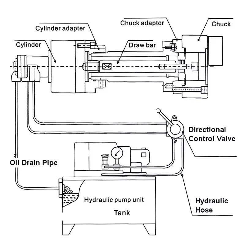
A typical hydraulic power chuck system includes the chuck body, master jaws, top jaws or soft jaws, drawbar or draw tube, rotary hydraulic cylinder and machine control. When hydraulic pressure moves the rotary cylinder piston, the drawbar transfers axial movement to the chuck. Inside the chuck, a wedge or similar mechanism converts that movement into jaw opening or closing.
The basic sequence is:
- The workpiece is loaded into the chuck.
- The machine or operator sends a clamp signal.
- The rotary cylinder moves the drawbar or draw tube.
- The chuck mechanism moves the jaws.
- The jaws clamp the workpiece on the selected surface.
- The machine confirms the clamped state before machining.
- After machining, the chuck releases and the workpiece is unloaded.
This sequence sounds simple, but the matching details matter. If the drawbar stroke is wrong, the jaws may not open or close fully. If the spindle nose, cylinder force, jaw contact or hydraulic pressure is not matched correctly, the clamping result may be unstable.
Main components of a CNC lathe power chuck system
| Component | Function | Selection note |
|---|---|---|
| Chuck body | Holds the jaw mechanism and connects to the spindle | Must match spindle nose, chuck size and workpiece type |
| Master jaws | Transfer chuck movement to top jaws or soft jaws | Jaw stroke and jaw serration must be checked |
| Top jaws / soft jaws / hard jaws | Contact the workpiece | Select according to workpiece surface, accuracy and cutting load |
| Drawbar or draw tube | Transfers actuator movement into the chuck | Thread, length and stroke are critical |
| Rotary hydraulic cylinder | Provides hydraulic actuation while the spindle rotates | Must match chuck type, stroke and push / pull force |
| Pneumatic actuator | Provides air-powered actuation for pneumatic chucks | Air pressure and holding method must be reviewed |
| Adapter or back plate | Connects chuck to spindle or mounting interface | Must be machined and checked correctly |
| Machine signal | Confirms chuck open / close state in CNC cycle | Important for automation and safe machining sequence |
A power chuck problem is often not caused by the chuck alone. It may come from drawbar length, cylinder stroke, jaw setup, spindle mounting, hydraulic pressure, part geometry or machine signal logic.
Power chuck vs manual chuck
A manual chuck is simple and flexible. It is often suitable for repair work, trial machining, toolroom use, small batches and workpieces that change frequently. The operator tightens the chuck with a wrench and controls the clamping feel manually.
A power chuck is better suited for repeated production. Once the chuck, actuator, jaws and machine sequence are set correctly, the chuck can open and close with repeatable timing. It can also work with a foot pedal, CNC program, robot or gantry loader.
| Item | Manual chuck | Power chuck |
|---|---|---|
| Actuation | Hand tightened | Hydraulic, pneumatic or powered |
| Typical use | Low-volume, flexible jobs | CNC production and repeated cycles |
| Automation | Limited | Easier to integrate |
| Setup cost | Lower | Higher because cylinder, drawbar and control are involved |
| Clamping consistency | Depends on operator | More repeatable when correctly set |
| Typical fit | Trial work, repair, flexible setup | Batch turning, robot loading, stable production process |
A manual chuck can still be the better choice when the job changes often and production volume is low. A power chuck is usually reviewed when cycle time, repeat clamping, machine control or automation becomes important.
Hydraulic power chuck vs pneumatic power chuck
A hydraulic power chuck uses hydraulic pressure. It is commonly selected for CNC turning where stronger and more stable clamping is needed. It usually works with a rotary hydraulic cylinder, hydraulic station and drawbar or draw tube.
A pneumatic power chuck uses compressed air. It may be selected where air actuation is easier to install, where the workpiece is lighter, where the process is cleaner, or where the clamping load is moderate. Pneumatic systems still require careful review of air pressure, leakage, holding condition and workpiece stability.
| Factor | Hydraulic power chuck | Pneumatic power chuck |
|---|---|---|
| Actuation medium | Hydraulic oil | Compressed air |
| Typical clamping capability | Often selected for stronger clamping and heavier cutting | Often reviewed for lighter or cleaner actuation needs |
| Machine integration | Common on CNC lathes | Depends on air circuit and chuck design |
| Maintenance focus | Oil pressure, cylinder, seals, drawbar | Air pressure, leakage, valve and holding method |
| Typical product family | Hydraulic chucks and special hydraulic chucks | Pneumatic chucks and air-actuated fixtures |
Hydraulic is not automatically better in every case, and pneumatic is not automatically too weak. The correct choice depends on workpiece size, cutting load, cycle time, machine interface and available actuation system.
Through-hole vs solid power chuck
A through-hole power chuck, also called a hollow chuck, allows bar stock, tube stock or long shaft material to pass through the spindle. It is commonly used when the workpiece is loaded from the rear of the spindle or when long material must extend through the chuck and spindle bore.
A solid power chuck, also called a closed-center chuck, does not provide a through passage. It is often selected for short shafts, discs, sleeves and individual blanks where rear feeding is not required. It is commonly paired with a solid rotary cylinder. When a manual chuck is converted to hydraulic clamping and the process does not require a through hole, a solid chuck may reduce system cost.
Vertical lathe applications and large-diameter hydraulic chucks are often reviewed as solid structures, but the final selection still depends on the machine, workpiece and loading method.
| Selection question | Through-hole power chuck | Solid power chuck |
|---|---|---|
| Does material pass through the spindle? | Yes, commonly | No |
| Typical workpiece | Long shafts, bar stock, tubes | Short shafts, discs, sleeves |
| Matching cylinder | Hollow rotary cylinder | Solid rotary cylinder |
| Rear loading | Possible when machine allows | Not the main use |
| Cost consideration | Needed when through-hole function matters | Can be more economical when through hole is unnecessary |
2-jaw, 3-jaw and 4-jaw power chucks
Jaw count should be selected from the workpiece shape and clamping surfaces.
A 3-jaw power chuck is commonly used for round, cylindrical and shaft-type workpieces. It is the most common layout for general CNC lathe turning.
A 4-jaw power chuck is commonly reviewed for square, rectangular, four-sided or workpieces that need four-point support. It can also help when the part geometry does not suit a standard 3-jaw contact pattern.
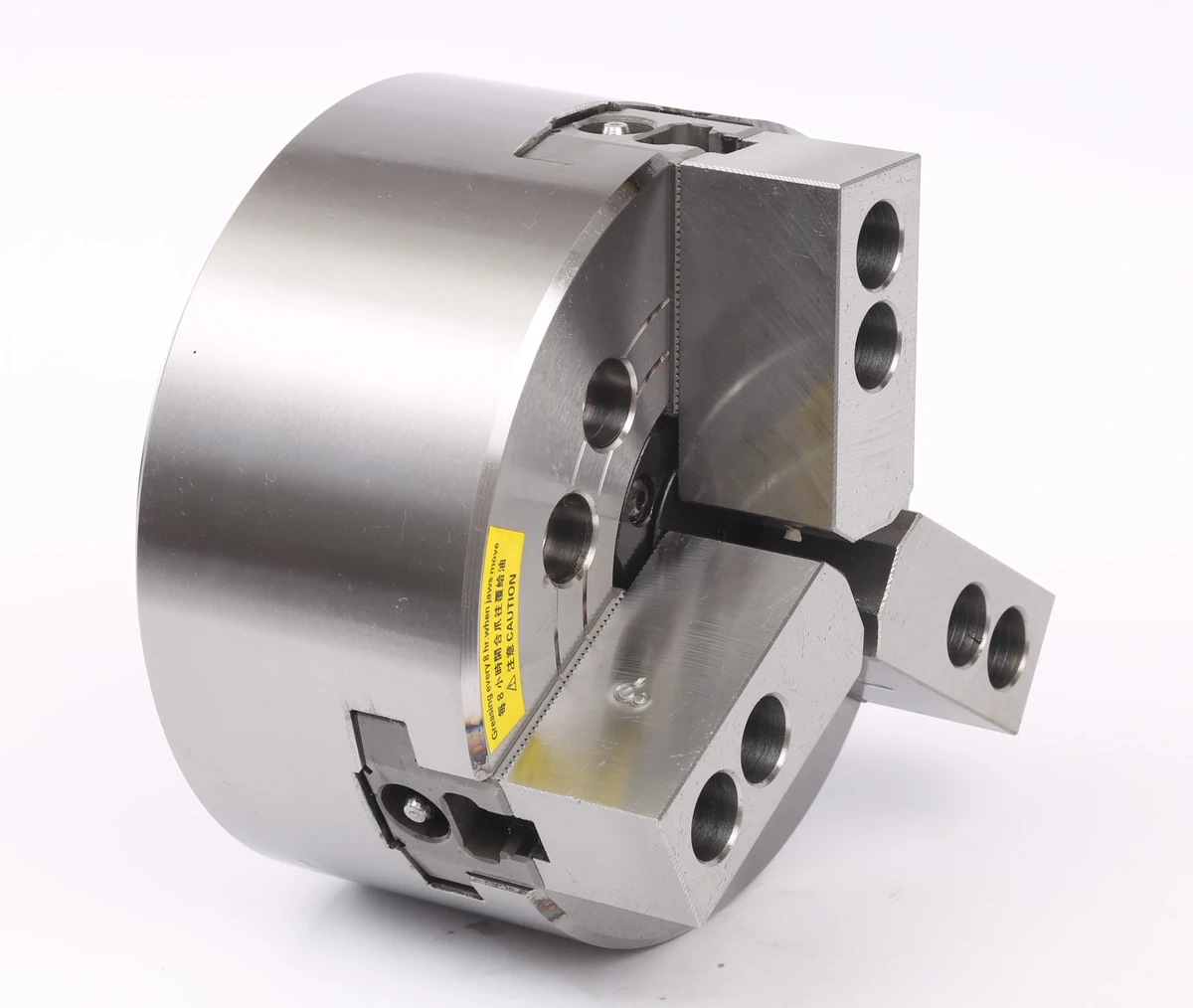
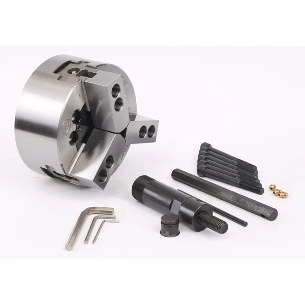
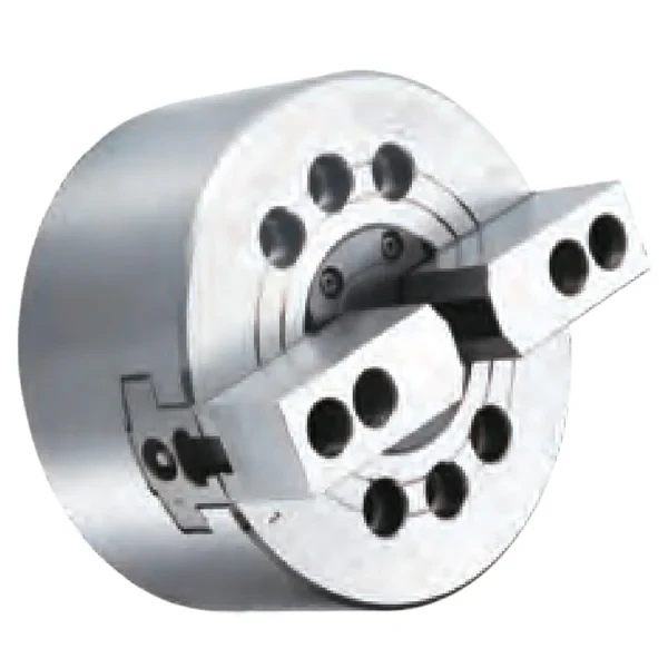
A 2-jaw power chuck is often used for shaped parts where only two opposing sides can be clamped, or where the workpiece requires custom jaws and non-round support.
| Jaw count | Common use | Selection note |
|---|---|---|
| 2-jaw | Opposing-side or shaped workpieces | Often needs custom jaws |
| 3-jaw | Round shafts, tubes, cylindrical parts | General CNC turning layout |
| 4-jaw | Square, rectangular or four-sided parts | Useful when 4-point support is needed |
These are common starting points, not absolute rules. The final decision should be based on the workpiece drawing, clamping surface, machining force and required datum.
Soft jaws vs hard jaws
Hard jaws are usually used for rougher clamping, raw stock or situations where gripping durability matters more than surface finish. The user-confirmed hardness reference for hard jaws is about HRC 55. They are useful for rough machining and less accuracy-sensitive holding, but they may leave marks on finished surfaces.
Soft jaws are usually made with lower hardness material and then machined to match the workpiece. The user-confirmed hardness reference is about HRC 25–35. Soft jaws are suitable when the workpiece has already been rough machined, when better contact is needed, or when the clamping surface must match the workpiece more closely.
| Jaw type | Typical use | Risk to check |
|---|---|---|
| Hard jaws | Rough stock, lower accuracy roughing, durable gripping | Jaw marks and limited surface matching |
| Soft jaws | Finished or semi-finished parts, better contact, repeat location | Must be machined correctly for the part |
| Custom jaws | Irregular parts or special support needs | Requires drawing and application review |
For thin-wall or deformation-sensitive parts, the jaw material alone is not enough. Contact area, clamping force, workpiece wall thickness and cutting direction must also be reviewed.
Standard power chuck vs application-specific power chuck
A standard hydraulic or pneumatic power chuck is suitable for many round, shaft, tube and general turning applications. But some workpieces need a special workholding structure.
Application-specific power chucks may be reviewed when the workpiece needs pull-back seating, floating compensation, ball lock support, face clamping, pipe-thread holding or multi-angle positioning.
Examples include:
- drawdown or pull-back chuck for axial seating;
- ball lock chuck for irregular support;
- floating compensation chuck for uneven blanks or support variation;
- finger chuck for face clamping or special end-face support;
- indexing chuck for multi-angle valve, tee and elbow machining.
The main article should not treat all these structures as the same. Each solves a different workholding problem.
When a standard power chuck is not the right choice
A standard power chuck may not be the right choice when the workpiece has very thin walls, unstable cast surfaces, irregular shapes, several machining directions, high deformation risk, limited jaw contact or strict axial seating requirements.
For example:
- If the part must be pulled against a locating face, review a drawdown or pull-back chuck.
- If the part has uneven casting surfaces, review floating or special support.
- If the outside surface must remain open for machining, review internal clamping or expanding mandrels.
- If the part is thin or surface-sensitive, review soft jaws, rubber-flex collets, diaphragm chucks or custom fixtures.
- If the part needs several angular positions, review indexing chucks.
- If the process is low volume and changes frequently, a manual chuck may still be practical.
The correct workholding solution is not the one with the largest chuck size or highest catalog force. It is the one that matches the part, machine and process.
Power chuck selection checklist
Before selecting a power chuck, confirm the following:
- workpiece drawing;
- material and hardness;
- outside diameter and inside diameter;
- workpiece length and weight;
- clamping surface;
- required datum or locating face;
- roughing or finishing operation;
- required jaw type: hard jaw, soft jaw or custom jaw;
- machine model;
- spindle nose;
- spindle bore;
- drawbar or draw tube thread;
- available drawbar stroke;
- hydraulic or pneumatic actuator type;
- rotary cylinder push / pull force;
- maximum spindle speed requirement;
- automation or robot loading requirement;
- clamping confirmation signal;
- production volume and changeover frequency.
The chuck, cylinder, drawbar, jaws and machine control should be reviewed as one system.
What information is needed for review?
For KORRETTO workholding review, send the workpiece drawing, material, clamping position, required accuracy, machining process, machine model, spindle interface, available cylinder information and whether the process needs rear feeding, automation or special positioning.
If the current problem is part slipping, jaw marks, deformation, poor repeatability, short jaw stroke, long changeover time or inconsistent clamping, include that information as well.
Related KORRETTO pages
FAQ
What is a power chuck?
A power chuck is a lathe chuck that uses hydraulic, pneumatic or another powered actuation source to open and close the jaws. It is commonly used on CNC lathes for repeated clamping, automation and batch machining.
What is the difference between a power chuck and a manual chuck?
A manual chuck is tightened by hand with a wrench. A power chuck uses a cylinder or powered actuator, making it more suitable for repeated clamping cycles, CNC control and automated production.
Is a hydraulic chuck a power chuck?
Yes. A hydraulic chuck is one of the most common types of power chuck. It usually works with a rotary hydraulic cylinder and drawbar or draw tube to clamp and release the workpiece.
What is the difference between hydraulic and pneumatic power chucks?
A hydraulic power chuck uses hydraulic pressure and is often selected for stronger and more stable clamping. A pneumatic chuck uses compressed air and may be reviewed for lighter, cleaner or faster actuation conditions. Final selection depends on workpiece size, cutting load and machine conditions.
When should I choose a through-hole power chuck?
Choose a through-hole power chuck when the workpiece is a long shaft, bar stock, tube or part that needs to pass through the spindle. It is commonly matched with a hollow rotary cylinder and rear feeding process.
When is a solid power chuck more suitable?
A solid power chuck is often suitable for short shafts, discs, sleeves and individual blanks where spindle-through loading is not required. It may also be reviewed when converting a manual chuck to hydraulic clamping and a through hole is unnecessary.
Should I use a 2-jaw, 3-jaw or 4-jaw power chuck?
A 3-jaw chuck is commonly used for round and cylindrical workpieces. A 4-jaw chuck is often reviewed for square, rectangular or four-sided parts. A 2-jaw chuck may be used when only two opposing sides can be clamped or when the workpiece has a special shape.
What information is needed to select a power chuck?
Provide the workpiece drawing, material, clamping surface, OD and ID, machine model, spindle nose, spindle bore, drawbar or draw tube information, hydraulic or pneumatic actuator data, required speed, jaw type and automation requirement.