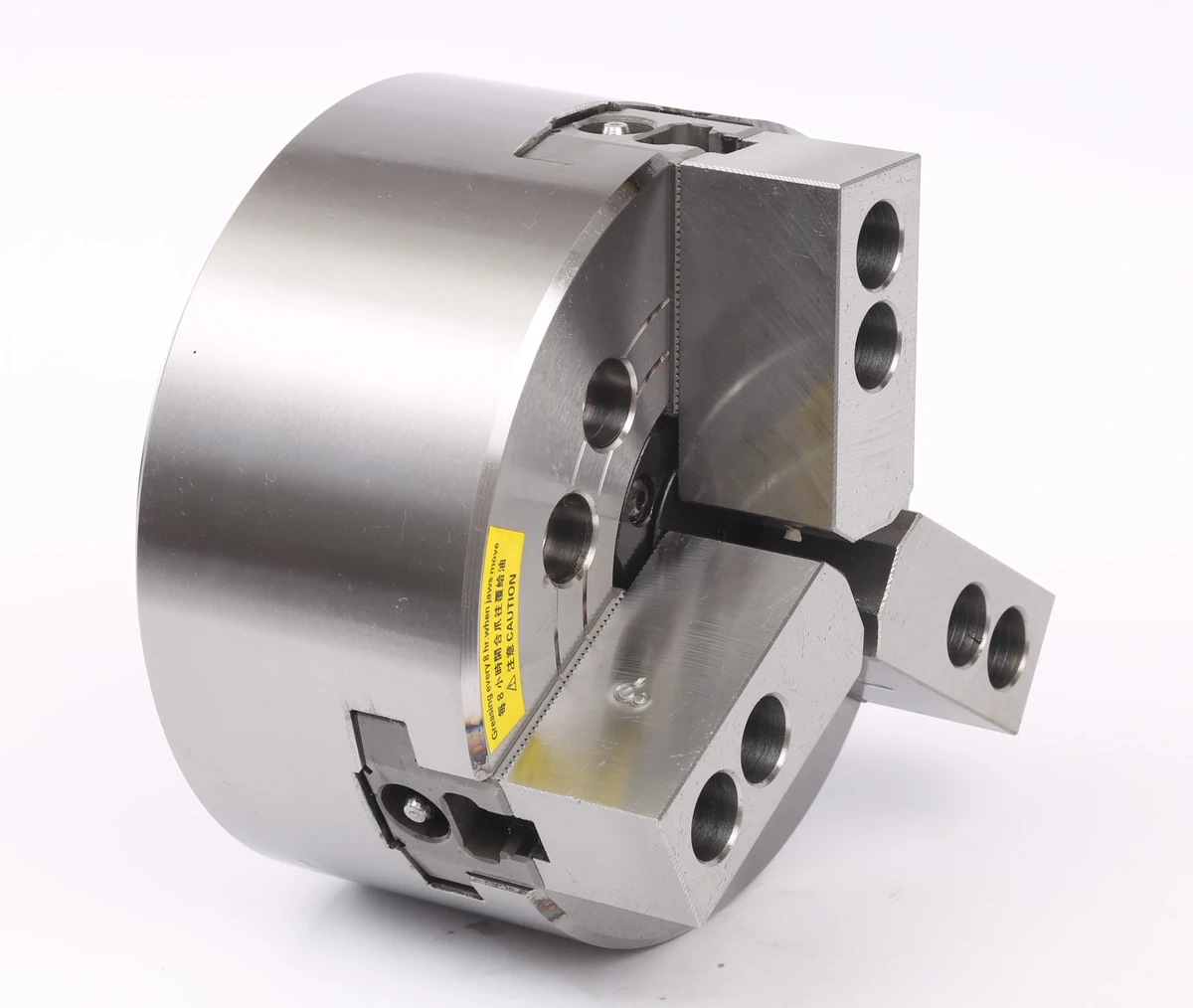
Power Chuck
Power Chuck Clamping Force and Hydraulic Pressure: What Affects CNC Lathe Workholding
Hydraulic pressure is not the same as power chuck clamping force. It is only one input in the clamping system. The final gripping result depends on the rotary cylinder, drawbar or draw tube, chuck mechanism, jaw stroke, top jaw position, jaw contact area, workpiece rigidity and machining load.
A part can still slip even when hydraulic pressure seems high if the jaws do not contact the workpiece correctly, the gripping diameter is unsuitable, the cutting direction creates axial pull, the workpiece surface is unstable, or the part deforms during clamping.
Clamping force review should be based on the complete chuck system and application data, not only on pressure. Final pressure and force data should follow the chuck supplier, cylinder supplier, machine builder and project engineering requirements.
Scope and Safety Boundary
A power chuck is part of a rotating CNC machine workholding system. Clamping force review may involve hydraulic or pneumatic actuation, moving jaws, drawbar or draw tube connection, machine-side confirmation signals and safety interlocks.
This article is a technical review checklist. It does not provide hydraulic pressure adjustment, machine parameter changes, PLC wiring, interlock modification, repair instructions or chuck disassembly steps. Machine-specific pressure and force data should be confirmed with qualified personnel and supplier documents.
Hydraulic Pressure Is Not the Same as Jaw Clamping Force
Hydraulic pressure is the pressure supplied to the actuator. In a hydraulic power chuck system, this pressure acts on the rotary hydraulic cylinder and creates actuator thrust.
That actuator thrust is transferred through the drawbar or draw tube to the chuck body. The chuck mechanism then converts axial movement and force into jaw movement and gripping force.
Because the system includes several mechanical interfaces, hydraulic pressure should not be treated as the same thing as jaw clamping force. The actual workholding result also depends on jaw contact, gripping diameter, top jaw position, workpiece rigidity and cutting load.
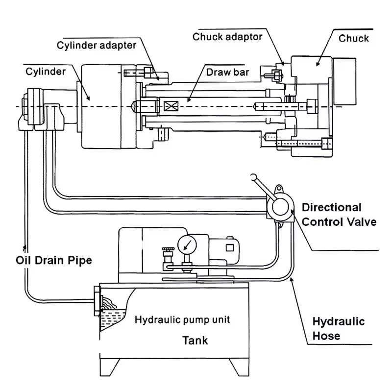
How Rotary Cylinder, Drawbar and Chuck Body Work Together
The rotary hydraulic cylinder provides the powered actuation while the spindle rotates. It connects to the chuck through a drawbar or draw tube. The chuck body converts that rear-side movement into jaw movement at the front.
For clamping force review, the cylinder, drawbar or draw tube and chuck should be checked as a matched system. If cylinder thrust, actuator stroke, drawbar connection or chuck mechanism data do not match, the jaw movement and gripping result may not meet the application requirement.
For a full system explanation, see hydraulic power chuck and rotary cylinder system.
Hydraulic pressure as system input
Hydraulic pressure is the input condition. It should be reviewed with the cylinder model, pressure range, machine hydraulic system and supplier requirements.
Rotary cylinder thrust and stroke
The rotary cylinder produces thrust and stroke. These values need to match the chuck mechanism and the required open / close movement.
Drawbar or draw tube force transfer
The drawbar or draw tube transfers rear-side actuator movement to the chuck. Connection data, length, thread or interface details should be confirmed for the actual machine.
Chuck mechanism and jaw movement
The chuck mechanism converts actuator movement into master jaw and top jaw movement. Jaw movement, gripping diameter and top jaw position affect how the part is actually held.
What Affects Actual Gripping Result
The gripping result at the workpiece is influenced by the complete system from actuator input to jaw contact. The table below summarizes the main review points.
| Factor | Why it matters |
|---|---|
| Hydraulic pressure | Input condition for the actuator, not the final gripping result by itself. |
| Rotary cylinder thrust | Provides the rear-side force available to operate the chuck. |
| Drawbar or draw tube | Transfers actuator movement and force to the chuck. |
| Chuck mechanism | Converts axial movement into jaw movement and gripping force. |
| Jaw stroke | Determines available jaw movement and usable clamping range. |
| Top jaw position | Affects leverage, contact condition and gripping diameter. |
| Jaw contact area | Determines how force is distributed on the workpiece. |
| Workpiece rigidity | Thin or weak parts may deform before stable clamping is reached. |
| Surface condition | Rough, slippery or unstable surfaces may reduce effective holding. |
| Cutting direction and load | Machining load may create radial or axial force that changes holding requirement. |

Jaw Stroke, Top Jaw Position and Gripping Diameter
Jaw stroke does not equal clamping force, but it affects whether the chuck can clamp the workpiece within a usable range. If the part is clamped near the end of available travel, jaw movement and contact may not be stable.
Top jaw position and gripping diameter also matter. A jaw setup that works for one diameter may not provide the same contact result at another diameter. Before judging pressure, check whether the top jaws, gripping diameter and available stroke match the workpiece.
For more detail, see jaw stroke and clamping range.
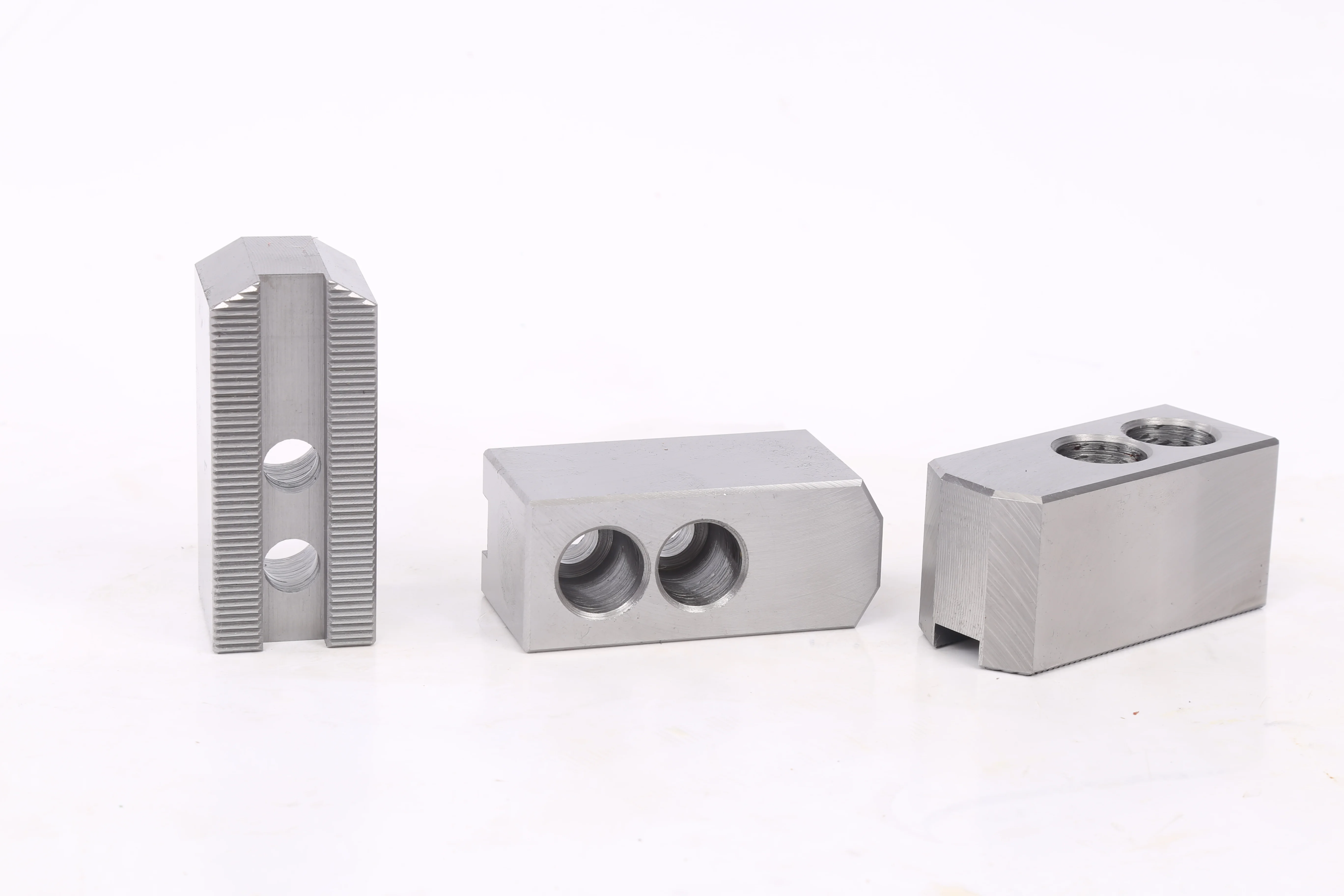
Soft Jaws, Hard Jaws and Contact Area
Soft jaws and hard jaws can change the actual clamping result because they affect contact area, surface support and jaw marks.
Soft jaws can be formed to match the workpiece profile and increase contact consistency. Hard jaws may be suitable for rough stock or durable general gripping. The correct choice depends on the workpiece surface, machining load, gripping diameter and repeat clamping requirement.
For more detail, see soft jaws vs hard jaws and soft jaw forming methods.
Workpiece Rigidity, Thin-Wall Parts and Deformation Risk
A higher clamping force is not always better. Thin-wall parts, sleeves, rings, soft materials and finish-machined surfaces may deform when the clamping force is too high or the contact area is too small.
In these cases, the review should include contact width, part wall thickness, locating datum, machining load, support direction and whether a special chuck or custom jaw is needed.
If the workpiece deforms before stable cutting is achieved, adding more pressure may make the result worse.
Why a Part May Slip Even When Pressure Seems High
A part may slip even when hydraulic pressure seems high because pressure is only one part of the system. Common causes include small jaw contact area, wrong gripping diameter, unsuitable top jaw position, poor surface condition, unfavorable cutting direction, insufficient axial support, part deformation or a mismatch between the cylinder, drawbar and chuck.
Do not treat slipping as a reason to raise pressure automatically. The correct review starts with the workpiece, jaw contact, chuck mechanism, actuator system and machining load.
Hydraulic vs Pneumatic Chuck Force Review
Hydraulic and pneumatic chucks should both be reviewed as complete actuation systems, but the input source is different.
Hydraulic chucks use hydraulic pressure and a rotary hydraulic cylinder. Pneumatic chucks use compressed air and pneumatic actuation. Pneumatic systems may be suitable for certain parts and automation layouts, while hydraulic systems are commonly used where higher and more stable actuation force is required.
The choice should be based on the workpiece, machining load, actuation source, jaw movement, holding requirement and machine layout. Do not assume that one type is always better for every application. For a broader comparison, see hydraulic vs pneumatic power chucks.
What Information to Prepare for Clamping Force Review
Before asking for clamping force review, prepare:
- Machine brand and model
- Chuck model and size
- Hydraulic cylinder or pneumatic actuator model
- Working pressure range if already specified by the machine or supplier
- Drawbar or draw tube data
- Spindle nose and mounting interface
- Jaw type and jaw layout
- Top jaw position
- Jaw stroke and clamping range
- Workpiece drawing
- Workpiece material and surface condition
- Gripping diameter
- Locating datum
- Machining operation and cutting direction
- Roughing or finishing requirement
- Thin-wall or deformation concern
- Current slipping, marking or deformation symptom if applicable
- Photos or video of the current clamping condition if available
Common Mistakes
Common mistakes include treating hydraulic pressure as the same as jaw force, raising pressure before checking jaw contact, ignoring gripping diameter, using unsuitable top jaws, assuming soft jaws always solve slipping, and checking clamping force without reviewing cutting direction.
Another mistake is reviewing the chuck body alone. The rotary cylinder, drawbar or draw tube, chuck mechanism, jaws, workpiece and machining load should be reviewed together.
Related Power Chuck Resources
For the category overview, start with the power chuck overview. For the actuation path, see hydraulic power chuck and rotary cylinder system. For front-side movement checks, see jaw stroke and clamping range.
For jaw-related review, see soft jaws vs hard jaws and soft jaw forming methods. For symptoms after setup, see power chuck troubleshooting checks and power chuck runout and clamping accuracy. For mounting data, see power chuck bolt torque and mounting checks.
FAQ
Is hydraulic pressure the same as power chuck clamping force?
No. Hydraulic pressure is an input to the actuator. The final gripping result also depends on rotary cylinder thrust, drawbar or draw tube movement, chuck mechanism, jaw stroke, jaw contact and workpiece rigidity.
What affects actual jaw gripping force?
Actual gripping result is affected by actuator force, chuck mechanism, jaw stroke, top jaw position, gripping diameter, jaw contact area, workpiece rigidity, friction condition and cutting load.
Why can a workpiece slip even when pressure is high?
A workpiece may slip if jaw contact is too small, the gripping diameter is unsuitable, the surface condition is poor, the cutting direction creates axial pull, the jaws are not matched to the part, or the workpiece deforms during clamping.
Can soft jaws improve clamping stability?
Soft jaws can improve contact consistency when they are formed to match the workpiece profile and gripping diameter. They do not make the setup stable by themselves, because pressure, contact area, material and machining load still matter.
Can too much clamping force deform a part?
Yes. Thin-wall parts, sleeves, rings, soft materials and finished surfaces may deform if clamping force is too high or contact area is too small.
Does jaw stroke affect clamping force?
Jaw stroke is not the same as clamping force, but it affects the usable clamping range, top jaw position and whether the part is held at a stable gripping diameter.
Is pneumatic chuck force checked the same way as hydraulic chuck force?
The review logic is similar, but the input source is different. Hydraulic systems use hydraulic pressure and rotary cylinders. Pneumatic systems use compressed air and pneumatic actuators.
What information is needed for clamping force review?
Prepare the workpiece drawing, material, gripping diameter, machining load, chuck model, cylinder or actuator model, drawbar data, jaw setup, machine model and any slipping, marking or deformation symptoms.