Power Chuck Troubleshooting Guide
Power Chuck Troubleshooting Checks: Weak Clamping, Runout, Jaw Stroke and Open/Close Problems
Power chuck troubleshooting should start from the symptom, not from replacing the chuck body. Weak clamping, runout, short jaw stroke, open / close failure and clamp confirmation problems may come from different parts of the system.
Before judging the chuck body, check the jaws, workpiece contact, mounting interface, adapter plate, spindle nose, actuator stroke, drawbar or draw tube data, rotary cylinder or pneumatic actuation condition, machine-side sequence and confirmation signal.
Direct Answer and Review Scope
Power chuck troubleshooting should start from the symptom, not from replacing the chuck body. Weak clamping, runout, short jaw stroke, open / close failure and clamp confirmation problems may come from different parts of the system.
Before judging the chuck body, check the jaws, workpiece contact, mounting interface, adapter plate, spindle nose, actuator stroke, drawbar or draw tube data, rotary cylinder or pneumatic actuation condition, machine-side sequence and confirmation signal.
This article is a troubleshooting review checklist. It does not provide machine repair, hydraulic pressure adjustment, PLC wiring, interlock modification or chuck disassembly instructions.

Safety and Scope Boundary
A power chuck is part of a machine workholding system. Troubleshooting may involve moving machine parts, hydraulic or pneumatic actuation, machine control signals and safety interlocks.
Use this article only as a review checklist for communication with a supplier, machine builder or qualified engineer. Do not use it as a repair procedure. Machine-specific checks, pressure settings, signal logic and interlock behavior should be confirmed with the machine data and qualified personnel.
Quick Symptom Table
| Symptom | Common check direction | Related KORRETTO resource |
|---|---|---|
| Weak or unstable clamping | Jaw contact, workpiece seating, actuator condition, drawbar or cylinder match, part deformation | Soft jaws vs hard jaws; hydraulic power chuck system |
| Chuck does not open or close fully | Actuator stroke, drawbar or draw tube movement, jaw stroke, chips, top jaw position, machine sequence | Jaw stroke and clamping range; mounting interface and drawbar data |
| Runout after installation | Mounting face, adapter plate, spindle nose, jaws, workpiece datum, measurement point | Runout and clamping accuracy |
| Jaw stroke or clamping range problem | Master jaw travel, top jaw position, gripping diameter, loading clearance | Jaw stroke and clamping range |
| Clamp confirmation or automation alarm | Chuck-open / chuck-closed status, part seating confirmation, machine-side signal boundary | Power chuck automation checks |
| Through-hole or bar passage issue | Chuck bore, spindle bore, draw tube bore, rotary cylinder bore, bar diameter | Through-hole vs solid power chuck |
Weak or Unstable Clamping
Weak or unstable clamping does not always mean that the chuck body is defective. The first checks should include workpiece seating, jaw contact area, jaw condition, gripping diameter, top jaw position and whether the part is deforming during clamping.
Soft jaws should match the actual workpiece diameter and datum requirement. Hard jaws should be checked for contact condition, wear and suitability for the workpiece surface. If the jaws do not contact the workpiece correctly, the clamping result may be unstable even when the chuck body and actuator are usable.
The actuation system should also be reviewed. For hydraulic systems, the rotary cylinder, drawbar or draw tube and chuck mechanism should match. For pneumatic systems, the air supply condition, pneumatic actuation layout and holding logic should be checked during engineering review.
Chuck Does Not Open or Close Fully
If a power chuck does not open or close fully, check the actuator movement, drawbar or draw tube movement, jaw stroke, top jaw position and possible obstruction around the jaws.
The problem may appear at the chuck jaws, but the cause may be behind the spindle. In a hydraulic system, rotary cylinder stroke and drawbar movement are part of the open / close chain. In a pneumatic system, pneumatic actuation movement and holding logic should be reviewed.
Chips, debris, unsuitable top jaw position or an incorrect clamping range may also limit actual jaw movement. This article does not provide drawbar adjustment, cylinder disassembly, air circuit adjustment or repair steps.
Runout or Repeatability Problem
Runout and repeatability problems should be checked from the mounting datum forward to the workpiece. The mounting face, spindle nose, adapter plate, chuck locating surface, jaw contact, workpiece datum and measurement point can all affect the result.
A new chuck can still show runout if the mounting interface is not clean or aligned, the adapter plate is not suitable, the jaws are not matched to the workpiece, or the workpiece deforms during clamping.
For a deeper explanation, see Power Chuck Runout and Clamping Accuracy.
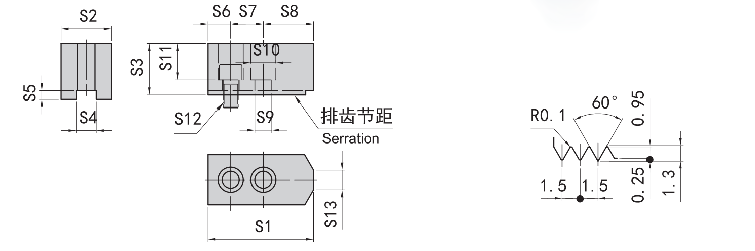
Jaw Stroke and Clamping Range Problems
Jaw stroke problems may appear as limited opening, insufficient loading clearance, unstable gripping, or a workpiece that cannot be clamped at the expected diameter.
Jaw stroke is not the same as actuator stroke. Actuator stroke comes from the cylinder, drawbar, draw tube or pneumatic mechanism. Jaw stroke is the movement available at the chuck jaws. The two are related through the chuck mechanism but should not be treated as the same data.
Before changing the chuck, review the master jaw travel, top jaw position, clamping diameter, jaw height, loading clearance and workpiece drawing. For more detail, see Power Chuck Jaw Stroke and Clamping Range.
Clamp Confirmation and Automation Alarms
Clamp confirmation problems should be reviewed as a machine-side status issue and a mechanical clamping issue. A chuck-open or chuck-closed signal may confirm a defined machine condition, but it does not always prove that the workpiece is seated correctly.
Automation alarms may be related to jaw opening, loading clearance, actuator movement, part seating, gripper interference, chips around the jaws or machine-side sequence timing.
This article does not provide PLC wiring, ladder logic, interlock modification or machine parameter instructions. Those details are machine-specific and should be handled by qualified personnel.
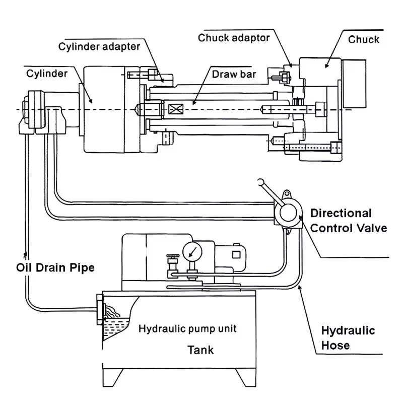
Hydraulic System Review Points
For hydraulic power chucks, review the chuck, rotary hydraulic cylinder, drawbar or draw tube, spindle interface and mounting layout as one system.
Important review items include rotary cylinder type, actuator stroke, drawbar or draw tube connection, rear clearance, through-hole requirement, mounting interface and whether the chuck reaches the intended open and closed positions.
For more detail, see How a Hydraulic Power Chuck Works with a Rotary Cylinder and Drawbar and Power Chuck Mounting Interface and Drawbar Data.
Pneumatic System Review Points
For pneumatic power chucks, review the chuck together with the pneumatic actuation method, air supply condition, jaw stroke, holding logic, loading clearance and workpiece support.
A pneumatic chuck should not be selected or judged only by the fact that compressed air is available. The actuation layout, part weight, contact area, jaw movement and confirmation logic should match the application.
For more detail, see Hydraulic vs Pneumatic Power Chucks and the pneumatic chuck series.
Through-Hole and Bar Passage Issues
If the problem is related to bar feeding, tube feeding or long workpieces, check the full passage through the system. The chuck bore alone is not enough.
Review the workpiece or bar diameter, chuck bore, spindle bore, draw tube bore and rotary cylinder bore. The smallest opening in the chain limits the practical passage. Also check whether the jaw setup and actuator layout support the required loading direction.
What Information to Send for Review
Before asking for troubleshooting review, prepare:
- Machine brand and model
- Chuck model and size
- Hydraulic cylinder, pneumatic actuator or air cylinder model
- Spindle nose and mounting interface
- Adapter plate or back plate information
- Drawbar or draw tube data
- Jaw type, jaw drawing or jaw photos
- Workpiece drawing and material
- Clamping diameter and gripping surface
- Description of the symptom
- Photos or video of open / close condition
- Measurement point if runout is involved
- Automation type and clamp confirmation requirement, if applicable
- Current setup photos from the front and rear side, if available
Common Mistakes
Common mistakes include assuming the chuck body is defective before checking jaws and actuator, replacing a chuck by outside diameter only, ignoring the adapter plate or spindle nose, confusing jaw stroke with actuator stroke, checking chuck bore but not the full through-spindle path, and assuming clamp confirmation proves correct part seating.
Hydraulic and pneumatic chuck problems also should not be treated as identical. The review logic is similar, but the actuation source, actuator behavior and machine-side confirmation may be different.
Related Power Chuck Resources
Start with the power chuck overview for basic chuck types and selection logic. For actuator and spindle-side checks, review the hydraulic power chuck and rotary cylinder system, mounting interface and drawbar data, and power chuck automation checks.
For jaw and workpiece-related symptoms, see soft jaws and hard jaws, jaw stroke and clamping range, runout and clamping accuracy, through-hole vs solid power chuck, 2-jaw vs 3-jaw vs 4-jaw power chucks, and hydraulic vs pneumatic power chucks.
Related Resources
FAQ
Why is my power chuck not clamping strongly?
Weak clamping may be related to jaw contact, workpiece seating, jaw condition, actuator condition, drawbar or cylinder matching, part deformation or machine-side settings. The chuck body should be judged only after the full system is reviewed.
Why does my hydraulic chuck not open fully?
A hydraulic chuck may not open fully if actuator stroke, drawbar or draw tube movement, jaw stroke, top jaw position, chips or the machine sequence prevents full movement. These checks should be reviewed with the chuck drawing, actuator data and machine information.
Can runout come from jaws instead of the chuck body?
Yes. Runout can come from jaw contact, soft jaw preparation, hard jaw wear, workpiece datum, workpiece deformation, mounting face, adapter plate or spindle nose. The chuck body is only one possible source.
Is jaw stroke the same as drawbar stroke?
No. Drawbar stroke comes from actuator movement behind the spindle. Jaw stroke is the movement available at the chuck jaws. The two are related through the chuck mechanism but should be checked as different data.
Can clamp confirmation prove that the workpiece is seated correctly?
Not always. Clamp confirmation usually confirms a defined machine-side status, such as chuck closed. Workpiece seating, jaw contact and part position still need mechanical review.
What should be checked before replacing a power chuck?
Check the mounting interface, spindle nose, adapter plate, drawbar or draw tube data, cylinder or actuator match, jaw setup, workpiece condition and machine-side signals before replacing the chuck.
What information should I send for troubleshooting review?
Send the machine model, chuck model, actuator or cylinder model, spindle nose, drawbar data, jaw layout, workpiece drawing, clamping diameter, symptom description and photos or video of the current setup.
Are hydraulic and pneumatic chuck problems checked the same way?
The basic review logic is similar, but the actuation source is different. Hydraulic systems require cylinder, drawbar and hydraulic actuation review. Pneumatic systems require air supply, pneumatic actuation and holding logic review.