Power Chuck Installation Guide
Power Chuck Runout and Clamping Accuracy: What to Check After Installation
Power chuck runout after installation is not always caused by the chuck body itself. Runout and clamping accuracy should be checked as a complete system, including the spindle nose, mounting face, adapter plate, chuck mounting datum, jaws, jaw contact area, drawbar or actuator stroke, workpiece surface and measuring method.
A new power chuck can still show runout if the mounting face is not clean, the adapter plate is not aligned, the soft jaws are not prepared for the actual gripping diameter, the hard jaws are worn, the drawbar stroke is not suitable, or the workpiece is deformed during clamping. Before blaming the chuck body, review the mechanical interface, jaw setup and workpiece condition step by step.
What Runout Means on a Power Chuck
Runout is the measured deviation when the chuck, jaw set or clamped workpiece rotates. In a lathe application, runout may be measured at different places, such as the chuck mounting face, chuck body, master jaw, top jaw, soft jaw bore or workpiece surface.
These measurement points do not always show the same result. A chuck body may be mounted correctly, while the workpiece still shows runout because of jaw contact, part surface condition, jaw preparation or workpiece deformation.
Runout vs Clamping Repeatability vs Workpiece Deformation
Runout, clamping repeatability and workpiece deformation are related, but they are not the same problem.
Runout describes measured eccentricity during rotation. Clamping repeatability describes whether the workpiece returns to the same position after repeated clamping. Workpiece deformation describes shape change caused by clamping force, jaw contact, thin wall structure or unsupported surfaces.
A runout problem should be checked together with repeatability and deformation. If the part changes shape during clamping, the measured value may not reflect only chuck accuracy.
| Issue | What it means | Common check direction |
|---|---|---|
| Runout | Eccentric rotation measured at the chuck, jaws or workpiece | Mounting face, adapter plate, jaws, workpiece datum and measuring point |
| Clamping repeatability | Position changes after repeated open / close cycles | Jaw contact, jaw wear, loading method, actuator stroke and workpiece location |
| Workpiece deformation | The part changes shape during clamping | Wall thickness, jaw contact area, clamping diameter, support condition and cutting load |
Why a New Chuck Can Still Show Runout
A new power chuck can still show runout if the installation system is not correct. The chuck is only one part of the complete setup.
Common causes include a dirty or damaged mounting face, adapter plate error, spindle nose mismatch, incorrect locating fit, uneven bolt tightening, jaw mismatch, unsuitable top jaws, insufficient jaw contact area, workpiece surface error or an actuator stroke problem.
For this reason, installation checks should start from the spindle and mounting datum, then move forward to the jaws and workpiece.
Mounting Face, Spindle Nose and Adapter Plate Checks
The mounting face and spindle nose define the mechanical datum between the machine and the chuck. If this interface is not clean, aligned or correctly fitted, runout can appear even when the chuck body is suitable.
Check the spindle nose, mounting pilot, bolt pattern, locating face, adapter plate and rear mounting surface against the chuck drawing and machine data. If an adapter plate or back plate is used, both the spindle side and the chuck side should be reviewed.
For replacement projects, also check the existing chuck model, adapter plate drawing and machine spindle data before judging the new chuck.
Soft Jaws, Hard Jaws and Jaw Contact Area
Jaws have a direct effect on workpiece runout and clamping repeatability. Soft jaws are often used when the gripping surface needs to match a specific workpiece diameter or profile. Hard jaws are commonly used for general gripping, rough stock or repeated standard clamping.
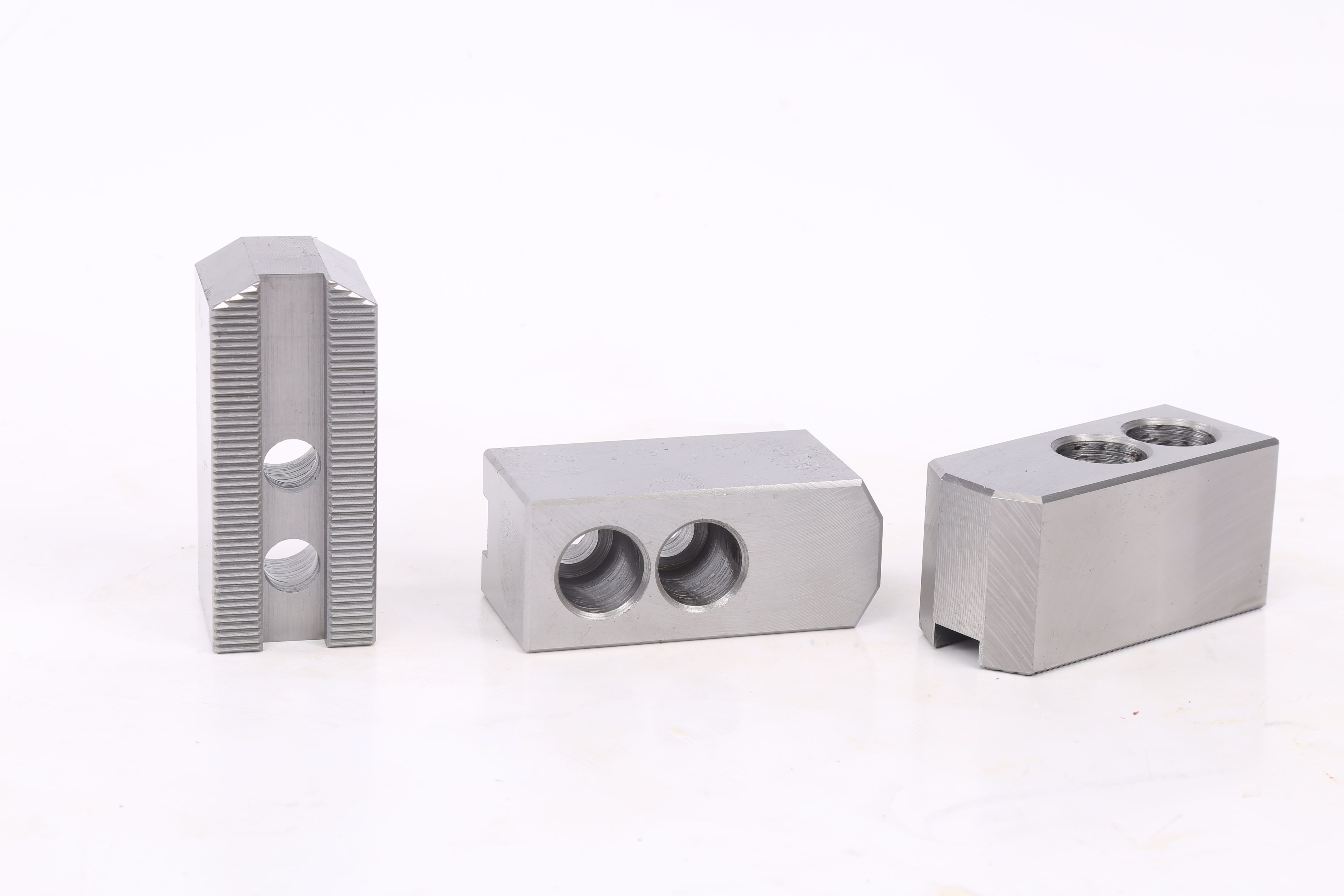
Soft jaws can help improve contact and repeatability when they are prepared for the actual clamping diameter and workpiece datum. Hard jaws can create runout or marks if the contact surface is worn, damaged or not suitable for the workpiece surface.
The jaw contact area, jaw height, gripping diameter, workpiece surface and loading method should be checked together. A jaw setup that works for one workpiece may not be suitable for another workpiece with a different diameter, surface or wall thickness.
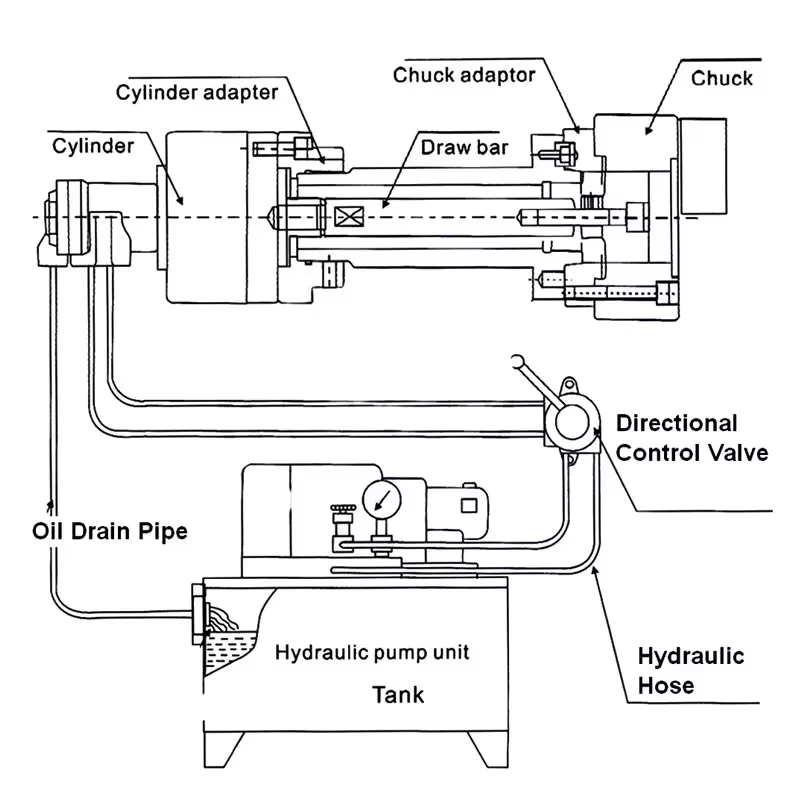
Drawbar, Rotary Cylinder and Actuator Stroke Checks
For hydraulic power chucks, the rotary cylinder, drawbar or draw tube transfers actuator movement to the chuck mechanism. If the stroke, connection or rear layout is not suitable, the chuck may not reach the intended open or closed position.
For pneumatic power chucks, the air supply, pneumatic actuation layout and holding logic should also be checked. Actuation issues may appear as incomplete jaw movement, inconsistent clamping or unstable part position.
This article does not provide drawbar, draw tube, air circuit or hydraulic system adjustment steps. These checks should be reviewed with the machine data, actuator data and chuck drawing.
Workpiece Surface, Loading Method and Clamping Diameter
The workpiece itself can also create runout or unstable clamping. A rough surface, casting variation, uneven stock allowance, short gripping length or unstable loading datum can affect the measured result.
The clamping diameter should match the jaw setup. The loading method should place the workpiece consistently against the intended datum. If the part is loaded by hand, robot or bar feeder, the part position before clamping should also be checked.
Before judging the chuck, confirm where the indicator is measuring and whether the measured surface is a reliable datum.
Thin-Wall Parts and Clamping Deformation
Thin-wall parts may deform during clamping. In this case, a measured runout problem may actually be caused by part deformation rather than chuck installation error.
For thin-wall rings, sleeves or tube parts, check wall thickness, clamping diameter, jaw contact width, support surface and cutting load. A larger contact area or a different jaw design may be needed, depending on the workpiece and machining operation.
Final selection should be confirmed with the workpiece drawing and test clamping when deformation risk is high.
Hydraulic or Pneumatic Actuation as a Secondary Check
Hydraulic or pneumatic actuation should be reviewed after the mechanical interface and jaw setup are checked. Actuation type alone does not determine runout.
A hydraulic chuck may show poor repeatability if the cylinder, drawbar or stroke condition is not suitable. A pneumatic chuck may show unstable clamping if the air supply, holding logic or jaw stroke is not suitable. In both cases, the actuator should be checked as part of the complete workholding system.
What to Check Before Blaming the Chuck Body
Before judging the chuck body, check:
- Machine spindle nose and mounting face
- Adapter plate or back plate condition
- Chuck mounting surface and locating fit
- Bolt pattern and installation condition
- Existing chuck model and replacement interface
- Master jaw movement and top jaw fit
- Soft jaw or hard jaw condition
- Jaw contact area and gripping diameter
- Workpiece surface and clamping datum
- Loading method and part seating
- Drawbar, draw tube or actuator stroke
- Rotary cylinder or pneumatic actuator data
- Measuring point and measuring method
- Workpiece deformation risk
Common Mistakes
Common mistakes include measuring only the workpiece without checking the mounting datum, blaming the chuck body before checking the adapter plate, using jaws that do not match the clamping diameter, ignoring workpiece surface error, confusing runout with repeatability, and treating thin-wall deformation as chuck inaccuracy.
A power chuck should be checked as part of the machine, jaw and workpiece system. The correct review sequence is usually mounting datum first, then jaws, actuator and workpiece condition.
Related Power Chuck Resources
For the broader category, start with the power chuck overview. For the hydraulic side, see the hydraulic power chuck and drawbar system. For replacement checks, review mounting interface and drawbar data.
For jaw and front-end setup, see jaw stroke and clamping range and soft jaws and hard jaws. For actuation comparison, see hydraulic vs pneumatic power chucks.
Related Resources
FAQ
Why does a new power chuck still have runout?
A new power chuck can show runout if the mounting face, spindle nose, adapter plate, jaw setup, workpiece datum or measuring point is not correct. The chuck body should be checked only after the full installation system is reviewed.
What is the difference between runout and clamping repeatability?
Runout is measured eccentricity during rotation. Clamping repeatability describes whether the workpiece returns to the same position after repeated clamping. A setup can have one problem, the other, or both.
Can soft jaws improve clamping accuracy?
Soft jaws can improve contact and repeatability when they are prepared for the actual workpiece diameter and datum. The result still depends on jaw contact area, workpiece rigidity, loading method and machining conditions.
Can hard jaws cause runout or jaw marks?
Hard jaws can affect runout or leave marks if the contact surface is worn, damaged or not suitable for the workpiece surface. They should be checked together with gripping diameter, part surface and jaw contact area.
Can drawbar stroke affect clamping accuracy?
Yes. If the drawbar, draw tube or actuator stroke does not allow the chuck to reach the correct open and closed positions, clamping can become unstable. Final checks should use the chuck drawing, actuator data and machine information.
What information is needed for a runout or accuracy review?
Prepare the machine model, spindle nose, adapter plate information, chuck model, jaw type, workpiece drawing, clamping diameter, measuring point, actuator or cylinder data and photos of the current setup if available.