Power Chuck Selection Guide
Hydraulic vs Pneumatic Power Chucks: How to Choose for CNC Lathe Workholding
Hydraulic and pneumatic power chucks are both powered workholding systems for CNC lathe clamping. The main difference is the actuation source. A hydraulic power chuck is operated by hydraulic pressure through a rotary hydraulic cylinder, drawbar or draw tube. A pneumatic power chuck is operated by compressed air through an air circuit or integrated pneumatic actuation layout.
The right choice depends on the workpiece, cutting load, required clamping stability, available hydraulic or air supply, machine layout, automation method, through-hole requirement, jaw setup and maintenance preference. Hydraulic chucks are commonly reviewed when higher clamping stability and conventional CNC turning systems are required. Pneumatic chucks are often reviewed when compressed air is convenient, the load is lighter or moderate, or the machine layout favors front-mounted or compact actuation.
What Hydraulic and Pneumatic Power Chucks Have in Common
Both hydraulic and pneumatic power chucks are designed to open and close the jaws by an external power source instead of manual wrench operation. Both must still be selected according to the workpiece, jaw count, jaw type, jaw stroke, clamping range, mounting interface and loading clearance.
The actuation method does not replace normal chuck selection checks. A hydraulic chuck can fail in a project if the drawbar, cylinder or mounting interface does not match. A pneumatic chuck can fail if the air supply, holding logic, jaw stroke or machine layout is not suitable.
Both Are Powered Workholding Systems
A powered chuck is selected as part of a complete machine-side system. The chuck body, jaws, actuator, mounting interface, workpiece loading method and machine control conditions should be reviewed together.
This article compares hydraulic and pneumatic actuation. For general power chuck types, see the power chuck overview.
Both Must Match Jaws, Stroke, Workpiece and Machine Layout
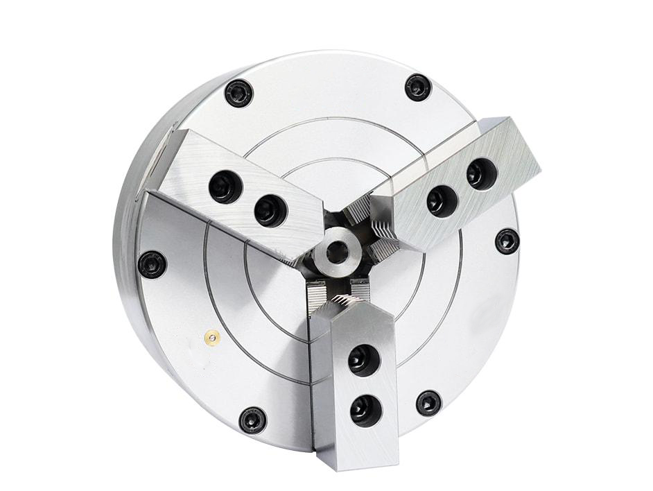
Jaw count and jaw type still matter. A 3-jaw chuck may be used for many round parts, a 2-jaw chuck may suit opposing surfaces or shaped parts, and a 4-jaw chuck may support square or four-sided workpieces. These choices are separate from hydraulic or pneumatic actuation.
Before selection, confirm the workpiece drawing, gripping diameter, jaw opening, loading clearance, machine mounting interface and available actuator space.
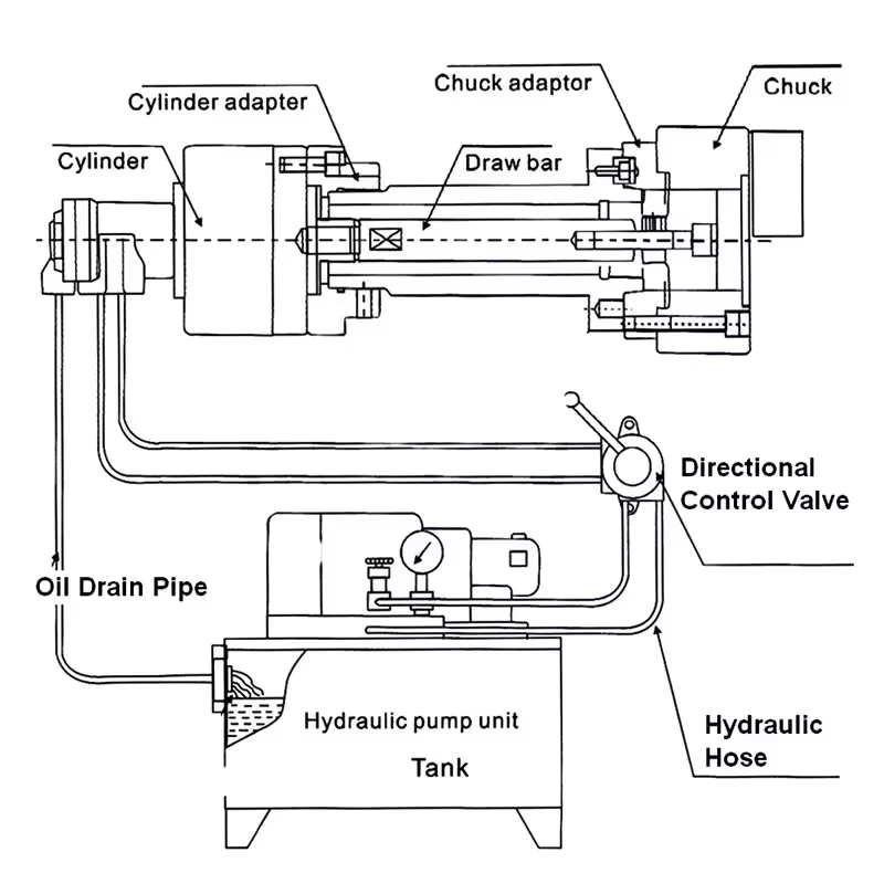
How a Hydraulic Power Chuck Is Actuated
A hydraulic power chuck is normally operated by a rotary hydraulic cylinder mounted behind the machine spindle. The cylinder moves a drawbar or draw tube. That movement is transferred through the chuck mechanism to open or close the jaws.
Hydraulic actuation is commonly used on CNC lathes where stable clamping, repeatable production and a standard rotary cylinder / drawbar system are required.
Rotary Hydraulic Cylinder, Drawbar or Draw Tube
The hydraulic cylinder, drawbar or draw tube and chuck must match as a system. The stroke, connection, mounting interface and rear clearance should be checked before replacement or retrofit.
Do not select the chuck by outside diameter alone. The hydraulic actuation chain is part of the selection.
When Hydraulic Actuation Is Usually Reviewed
Hydraulic actuation is usually reviewed when the application involves regular CNC turning, higher clamping stability requirements, existing hydraulic cylinder infrastructure, through-hole bar or tube layouts, or production work where the chuck must operate consistently over repeated cycles.
Final suitability still depends on the chuck model, cylinder data, machine interface, workpiece and machining operation.
How a Pneumatic Power Chuck Is Actuated
A pneumatic power chuck uses compressed air as the actuation source. Depending on the design, the pneumatic mechanism may be integrated in the chuck body or connected through a pneumatic circuit.
Pneumatic chucks can be useful when compressed air is easier to provide than hydraulic actuation, when the workpiece load is lighter or moderate, or when the machine layout favors a compact, front-mounted or fixture-style clamping solution.
Compressed Air, Air Circuit and Holding Logic
A pneumatic chuck must be checked together with the air supply, open / close logic, holding method, jaw stroke and machine safety conditions.
This article does not provide air circuit, valve, PLC or interlock modification steps. Those details are machine-specific and should be reviewed during engineering confirmation.
Front-Mounted, Solid, Semi-Through and Through-Hole Pneumatic Layouts
Pneumatic chucks may be solid, semi-through-hole, through-hole, front-mounted or vertical depending on the chuck series and machine layout.
The structure should be selected based on workpiece loading direction, required center clearance, machine mounting space and jaw setup. Through-hole, semi-through and solid-center structure are layout choices; they are not the same as the actuation choice.
Hydraulic vs Pneumatic Power Chuck Comparison
| Selection factor | Hydraulic power chuck | Pneumatic power chuck |
|---|---|---|
| Actuation source | Hydraulic pressure through rotary cylinder, drawbar or draw tube | Compressed air through pneumatic mechanism or air circuit |
| Machine supply | Requires suitable hydraulic actuation system | Requires stable compressed air supply and control logic |
| Clamping stability | Often reviewed for higher clamping stability and regular CNC turning | Often reviewed for lighter or moderate loads, compact layouts or clean air-driven setups |
| System components | Chuck, rotary cylinder, drawbar / draw tube, hydraulic supply and machine interface | Chuck, air supply, pneumatic circuit or integrated actuation and machine interface |
| Through-hole options | Common in CNC lathe bar, tube or shaft applications when spindle and cylinder bore match | Available in selected front-mounted, semi-through or through-hole pneumatic layouts |
| Selection risk | Mismatched cylinder stroke, drawbar data or mounting interface | Insufficient air supply, holding logic, stroke or layout mismatch |
When to Choose a Hydraulic Power Chuck
A hydraulic power chuck is usually worth reviewing when the application needs higher clamping stability, regular CNC turning, existing hydraulic cylinder infrastructure, bar or tube handling, or a production setup that already uses drawbar or draw tube actuation.
Hydraulic selection should include the chuck model, spindle nose, rotary hydraulic cylinder, drawbar or draw tube data, jaw stroke, through-hole requirement and workpiece loading method.
When to Choose a Pneumatic Power Chuck
A pneumatic power chuck is usually worth reviewing when compressed air is convenient, the workpiece load is lighter or moderate, the machine or fixture layout benefits from a compact pneumatic actuator, or a front-mounted or vertical pneumatic chuck fits the application better.
Pneumatic selection should include the air supply, actuation method, jaw stroke, open / close confirmation, loading clearance, mounting interface and workpiece support condition.
Through-Hole and Solid-Center Considerations
Through-hole, semi-through-hole and solid-center structures should be checked separately from the actuation method.
A hydraulic chuck may be through-hole or solid-center. A pneumatic chuck may also be solid, semi-through or through-hole depending on the design. The correct structure depends on whether the workpiece must pass through the spindle, whether it is front-loaded, and whether the machine has enough bore and rear clearance.
Do not choose hydraulic or pneumatic actuation before confirming the workpiece loading path.
Automation and Loading Considerations
For automated loading, check the open / close sequence, signal confirmation, part loading path, jaw opening, robot or loader clearance and machine guard clearance.
Hydraulic and pneumatic chucks can both be used in automation depending on the machine and chuck design. The important point is to check the full system, not only the chuck body. This article does not provide PLC or air / hydraulic circuit modification instructions.
What to Check Before Selection
Before choosing hydraulic or pneumatic actuation, prepare:
- Workpiece drawing
- Material and machining operation
- Clamping diameter and tolerance requirement
- Expected cutting load
- Machine brand and model
- Spindle nose and mounting interface
- Available hydraulic system or air supply
- Existing rotary cylinder or pneumatic actuator information
- Drawbar or draw tube data if hydraulic actuation is used
- Through-hole, semi-through or solid-center requirement
- Jaw count and jaw type
- Jaw stroke and clamping range
- Loading method, such as front loading, bar feeding or robot loading
- Signal confirmation or automation requirement
- Maintenance preference and available machine space
Common Mistakes
Common mistakes include choosing by chuck size only, assuming hydraulic actuation is always the correct choice, assuming pneumatic actuation is enough whenever compressed air is available, ignoring holding logic, confusing through-hole structure with actuation type, and checking jaw count without checking stroke, clearance and machine layout.
For new selection or replacement, the chuck, actuator, machine interface and workpiece should be reviewed together.
Related Power Chuck Resources
For the broader category, start with the power chuck overview. For the hydraulic side, see the hydraulic power chuck and drawbar system. For center structure selection, compare through-hole vs solid power chuck.
For front-end chuck selection, review 2-jaw, 3-jaw and 4-jaw power chuck selection, soft jaws and hard jaws, jaw stroke and clamping range, and mounting interface and drawbar data.
Related Resources
FAQ
What is the difference between a hydraulic and pneumatic power chuck?
A hydraulic power chuck is actuated by hydraulic pressure through a rotary cylinder, drawbar or draw tube. A pneumatic power chuck is actuated by compressed air through a pneumatic mechanism or air circuit. The right choice depends on workpiece load, machine supply, layout and clamping requirements.
When should I choose a hydraulic power chuck?
A hydraulic power chuck is usually reviewed when the application needs higher clamping stability, regular CNC turning, an existing hydraulic cylinder system, or through-hole bar, tube or shaft handling.
When should I choose a pneumatic power chuck?
A pneumatic power chuck is usually reviewed when compressed air is convenient, the workpiece load is lighter or moderate, or the layout benefits from a compact, front-mounted or fixture-style pneumatic chuck.
Are pneumatic chucks suitable for CNC lathes?
Yes, pneumatic chucks can be suitable for CNC lathes when the air supply, holding logic, jaw stroke, clamping margin, mounting interface and workpiece loading method are properly checked.
Is hydraulic always stronger than pneumatic?
Hydraulic actuation is often reviewed for higher clamping stability requirements, but the final choice should not be made by actuation type alone. The specific chuck model, actuator, workpiece and machining load must be checked.
What information is needed before choosing hydraulic or pneumatic actuation?
Prepare the workpiece drawing, material, clamping diameter, machining load, machine model, spindle interface, hydraulic or air supply condition, through-hole requirement, jaw setup, loading method and automation requirement.