Power Chuck
Soft Jaw Forming Methods for CNC Lathe Chucks: Types, Steps and Accuracy Checks
Soft jaw forming means machining or preparing soft jaws so the gripping surface matches the workpiece diameter, profile and datum requirement. It is commonly used on CNC lathe chucks when repeat clamping, controlled contact area or reduced marking risk is needed.
The forming method should be selected according to the gripping direction, workpiece diameter, jaw position, chuck type and required contact surface. Common methods include forming plug use for outside diameter gripping, forming ring use for inside diameter gripping and forming jig use when the jaw position needs controlled support during preparation.
Soft jaw forming can improve contact consistency, but it does not confirm accuracy by itself. Runout and repeatability also depend on chuck condition, mounting interface, jaw stroke, workpiece rigidity, datum selection and measurement method.
What Soft Jaw Forming Means
Soft jaws are machinable chuck jaws prepared to match a workpiece more closely than standard hard jaws. Forming the soft jaws usually means cutting the jaw gripping surface while the jaws are held in a controlled condition.
The goal is not only to create a matching shape. The goal is to make the jaw contact stable, repeatable and suitable for the actual gripping diameter and machining process.
Why Soft Jaw Forming Affects Runout and Repeatability
Soft jaw forming affects how the part seats in the chuck. If the jaws are formed at the wrong diameter, held in the wrong direction or machined without suitable preload, the finished jaw surface may not contact the workpiece correctly.
Poor jaw contact can cause runout, jaw marks, part movement, poor repeatability or local deformation. A correct review should include jaw contact area, workpiece datum, gripping length, jaw stroke, clamping direction and part rigidity.
Before Forming Soft Jaws: Data to Confirm
Before soft jaw forming, confirm:
- Chuck model and chuck size
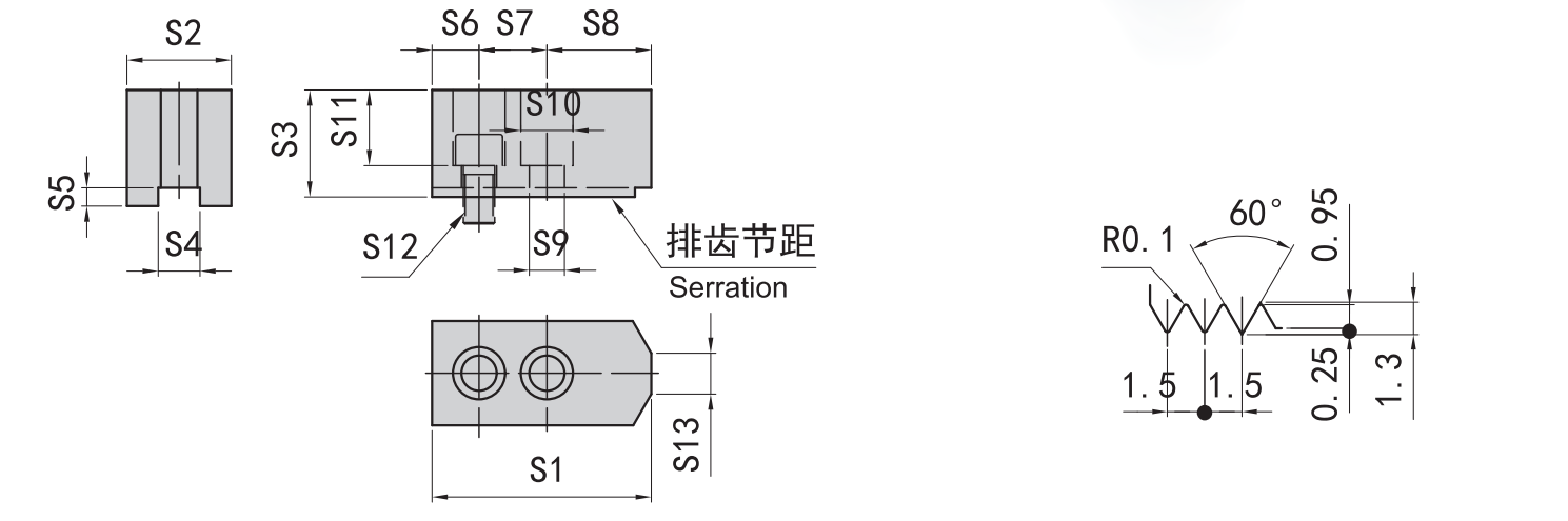
- Jaw interface and serration type
- Number of jaws
- Workpiece drawing
- Workpiece material and surface condition
- Internal or external gripping direction
- Target gripping diameter
- Workpiece datum surface
- Required jaw contact area
- Available jaw stroke and clamping range
- Top jaw position
- Loading clearance
- Thin-wall or deformation risk
- Whether the operation is rough machining or finish machining
The jaw drawing and chuck model should be checked before machining the soft jaws. The same soft jaw blank may not fit every chuck interface.
Common Soft Jaw Forming Methods
Soft jaw forming is selected by clamping direction and how the jaw surface will contact the part. The table below gives a practical comparison.
| Method | Typical use | Main check direction |
|---|---|---|
| Forming plug method | Outside diameter gripping | Plug diameter, jaw preload direction, gripping diameter and trial contact |
| Forming ring method | Inside diameter gripping | Ring position, jaw opening direction, inner gripping diameter and contact stability |
| Forming jig method | Controlled jaw position during forming | Jig contact, jaw position, pin or bolt layout, forming stability and trial cutting result |
| Part-based review | Special profiles or sample parts | Workpiece datum, contact area, deformation risk and repeat loading position |
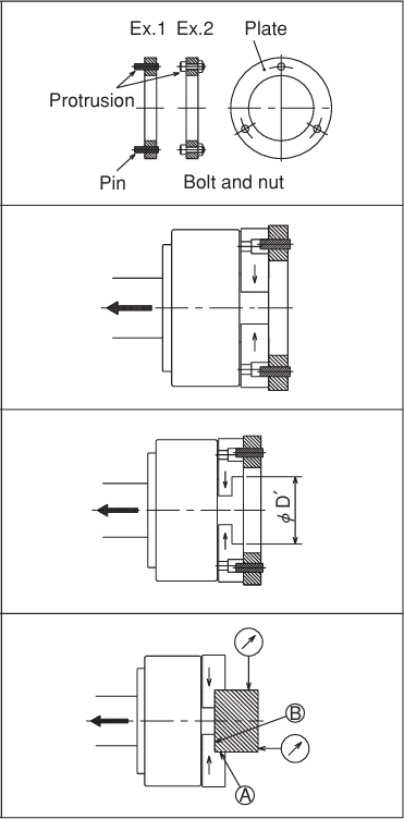
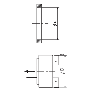
Forming Plug Method for Outside Diameter Gripping
The forming plug method is used when the finished jaws need to grip the outside diameter of the workpiece. A plug or reference piece is used to hold the jaws in a loaded condition before the jaw gripping surface is machined.
The important point is that the jaws should be formed under a condition similar to the final gripping direction. After forming, the workpiece should be checked for seating, contact area, jaw stroke margin and trial cutting behavior.
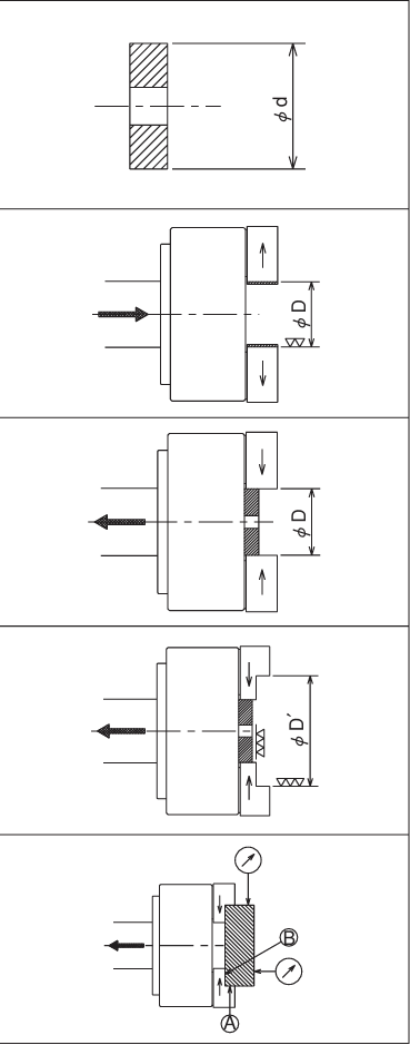
Forming Ring Method for Inside Diameter Gripping
The forming ring method is used when the jaws need to grip an inside diameter or expand against an internal surface. A ring helps hold the jaws at the intended forming position while the jaw contact surface is prepared.
The ring should be reviewed as a setup aid, not as a universal formula. The actual forming size depends on the chuck, jaw stroke, workpiece diameter and required contact surface.
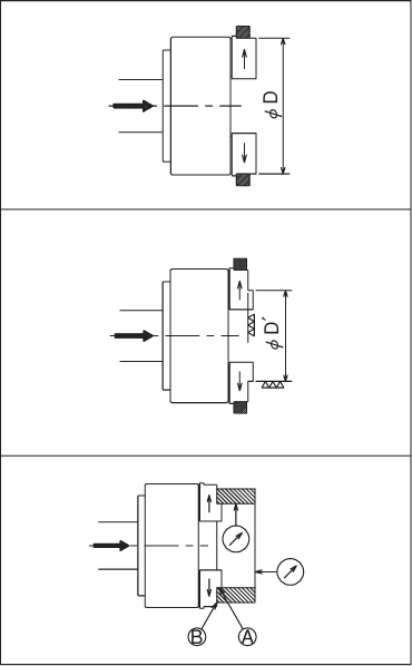
Forming Jig Method
A forming jig can be used when a controlled jaw position is needed during soft jaw preparation. The jig may use a ring-shaped plate, pins, bolts or other locating elements to keep the jaws in a stable forming condition.
This method is useful when the jaws need to be held consistently while the gripping surface is machined. The final jaw contact should still be checked with the actual workpiece or an approved reference part.
Internal Gripping vs External Gripping Considerations
External gripping and internal gripping load the jaws in different directions. The forming method should match the intended clamping direction.
For external gripping, the jaws close onto the outside of the workpiece. For internal gripping, the jaws expand or contact the inner surface. The jaw surface should be prepared so that the final clamping direction, gripping diameter and contact area are consistent with the real machining condition.
Jaw Contact Area, Gripping Diameter and Jaw Stroke
Jaw contact area and gripping diameter are central to soft jaw forming. If the jaws are formed too far from the real clamping diameter, the actual workpiece contact may be partial or unstable.
Jaw stroke also matters. The chuck must still have enough travel for loading, closing and safe clamping after the soft jaws are installed and formed. For more detail, see jaw stroke and clamping range.
Thin-Wall Parts and Deformation Risk
Thin-wall parts, sleeves and easily deformed workpieces need special attention. A soft jaw can increase contact area, but excessive or uneven clamping can still deform the part.
For these applications, the review should include workpiece wall thickness, contact width, support surface, machining load, datum location and whether a special chuck or application-specific fixture is more suitable.
Accuracy Checks After Soft Jaw Forming
After soft jaw forming, review:
- Whether the part seats against the intended datum
- Whether the jaw contact is stable and balanced
- Whether the workpiece slips during a trial check
- Whether jaw stroke remains within the usable range
- Whether loading clearance is still sufficient
- Whether the measurement point matches the machining requirement
- Whether runout or repeatability is checked at the correct datum
- Whether thin-wall parts show visible or measurable deformation
Do not judge the result from the jaw surface alone. The measured datum, workpiece rigidity and machine setup should match the actual machining requirement.
Common Mistakes to Avoid
Common mistakes include forming soft jaws at the wrong diameter, ignoring the final clamping direction, using the wrong jaw interface, leaving too little jaw stroke margin, using a contact area that is too small, assuming soft jaws always remove jaw marks, and judging runout without checking the workpiece datum and measurement point.
Soft jaw forming should be reviewed together with the chuck, jaws, workpiece and machining process.
What Information Is Needed for Review
Before asking for soft jaw or custom jaw review, prepare:
- Chuck model and size
- Jaw interface or jaw drawing
- Current soft jaw or hard jaw photos
- Workpiece drawing
- Workpiece material
- Internal or external gripping direction
- Target gripping diameter
- Required contact surface
- Locating datum
- Machining process
- Batch size or repeat clamping requirement
- Thin-wall or deformation concern
- Runout or repeatability requirement if already specified by the project
- Photos or video of the current clamping condition if available
Related KORRETTO Pages
For jaw selection background, see soft jaws vs hard jaws. For measurement and setup review, see power chuck runout and clamping accuracy, jaw stroke and clamping range, and power chuck troubleshooting checks.
For broader workholding context, see the power chuck overview and 2-jaw vs 3-jaw vs 4-jaw power chucks.
Related Resources
Jaw-specific PDF: Hard jaw and soft jaw datasheet.
FAQ
What is soft jaw forming?
Soft jaw forming means machining or preparing soft jaws so the gripping surface matches the workpiece diameter, profile and datum requirement. It is used to improve contact consistency and repeat clamping.
Why do soft jaws need to be machined before use?
Soft jaws are machinable blanks. They usually need to be prepared to match the actual workpiece diameter, clamping direction and contact surface before stable production use.
What is the difference between outside diameter and inside diameter soft jaw forming?
Outside diameter forming prepares jaws to close onto the outer surface of a workpiece. Inside diameter forming prepares jaws to grip or support an internal surface. The forming direction should match the final clamping direction.
How does jaw stroke affect soft jaw forming?
Jaw stroke affects whether the chuck can open, load the part and still clamp within the usable range after the soft jaws are installed and formed. Gripping diameter and top jaw position should be checked before forming.
Can soft jaw forming improve runout?
Soft jaw forming can improve contact consistency, but runout also depends on chuck condition, mounting interface, jaw stroke, workpiece rigidity, datum selection and measurement method. It should not be treated as a fixed accuracy fix.
What should be checked after forming soft jaws?
Check part seating, jaw contact, gripping diameter, jaw stroke margin, loading clearance, trial cutting behavior, measurement point and whether the workpiece deforms during clamping.
When should hard jaws be used instead?
Hard jaws may be suitable for rough stock, rough machining or applications where durable general gripping is more important than profile-matched contact. The choice depends on workpiece surface, load and chuck compatibility.
What information is needed before selecting or forming soft jaws?
Prepare the chuck model, jaw interface, workpiece drawing, material, gripping direction, target gripping diameter, datum surface, clamping surface, machining process and any runout or repeatability requirement already specified by the project.