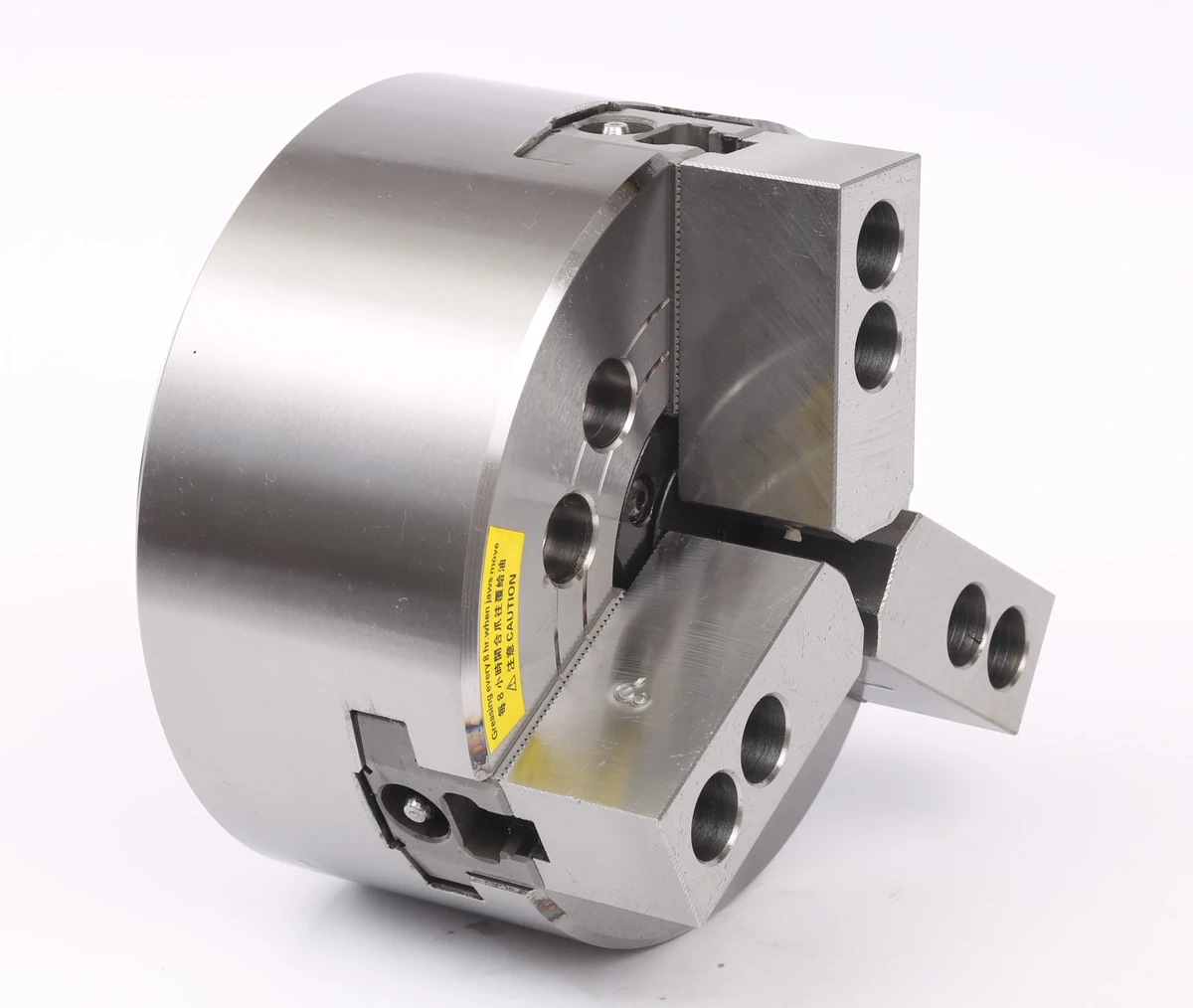
Power Chuck
Power Chuck Bolt Torque and Mounting Checks: What to Confirm Before Installation
Before installing or replacing a CNC lathe power chuck, bolt torque should be checked together with the mounting face, adapter plate, spindle nose, locating diameter, bolt pattern and rear-side actuator connection.
Bolt torque is only one part of the mounting review. A correct mounting result also depends on clean and suitable contact faces, matching back plate or adapter plate, correct bolt size and grade, suitable thread condition, proper chuck-to-spindle location and whether the rotary cylinder, drawbar or draw tube matches the chuck.
A torque table can be used as a reference, but final tightening torque should follow the bolt supplier, chuck supplier, machine builder and project engineering requirements.
Scope and Safety Boundary
A power chuck is part of a rotating machine workholding system. Mounting checks may involve heavy components, spindle interfaces, hydraulic or pneumatic actuators, moving jaws and machine safety interlocks.
This article is a mounting review checklist. It does not provide machine repair, chuck removal, hydraulic adjustment, PLC wiring, interlock modification or machine parameter instructions. Machine-specific installation work should be handled by qualified personnel according to machine builder and supplier documents.

Why Bolt Torque Matters in Power Chuck Mounting
Mounting bolts help hold the chuck or adapter plate against the mounting face. If the bolts are not suitable for the mounting condition, the chuck may not seat correctly or the clamping system may not remain stable during operation.
Bolt torque should be reviewed together with bolt size, bolt grade, thread engagement, thread condition, lubrication condition, contact face condition, adapter plate design and the machine builder's requirements.
Torque alone cannot correct an unsuitable mounting face, wrong locating diameter, damaged thread, incorrect adapter plate or mismatched spindle interface.
Reference Bolt Torque Table
This bolt tightening torque table is a reference only. Final tightening torque should follow the bolt supplier, chuck supplier, machine builder and project engineering requirements. The table does not define bolt grade, lubrication condition, thread condition, machine-specific requirements or special chuck requirements.
| Bolt size | Reference tightening torque |
|---|---|
| M5 | 7.5 N·m |
| M6 | 13 N·m |
| M8 | 33 N·m |
| M10 | 73 N·m |
| M12 | 107 N·m |
| M14 | 171 N·m |
| M16 | 250 N·m |
| M20 | 402 N·m |
The values above should not be used as the only installation authority. If the actual bolt grade, thread condition or machine requirement is not confirmed, the torque value should be confirmed with the bolt supplier, chuck supplier, machine builder or project engineer.
What the Bolt Torque Table Can and Cannot Tell You
The table can help identify a general torque reference by bolt size. It can be useful during quotation review, mounting data preparation or communication with an engineer.
The table cannot confirm whether a specific bolt is suitable for a specific chuck, spindle or machine. It also cannot replace supplier instructions for bolt grade, thread engagement, lubrication condition, tightening method or safety requirements.
If the bolt size, grade or mounting condition is not confirmed, do not guess the torque value. Confirm the data with the bolt supplier, chuck supplier, machine builder or project engineer.
Mounting Face, Adapter Plate and Spindle Nose Checks
Before the chuck is mounted, the spindle nose, mounting face, adapter plate or back plate should be reviewed. The surfaces should match the intended locating and contact structure.
The adapter plate connects the machine spindle side and the chuck side. If its locating diameter, face contact, bolt pattern or thickness is not suitable, the chuck may not seat correctly even when the bolt torque is correct.
For replacement projects, the spindle nose, existing chuck interface and adapter plate dimensions should be checked before ordering or machining a new plate. For deeper replacement data, see power chuck mounting interface and drawbar data.
Bolt Size, Grade, Thread Condition and Supplier Data
Bolt size alone is not enough. Bolt grade, thread condition, thread engagement, washer use, contact surface and lubrication condition may affect the required tightening torque.
The bolt supplier and machine builder should be treated as the authority for final bolt data. If the chuck supplier provides a specific mounting requirement, it should also be reviewed before installation.
Do not reuse bolts, threads or mounting holes without checking their condition when the application requires engineering review.
Power Chuck Body, Back Plate and Locating Diameter
The power chuck body should match the adapter plate or spindle mounting arrangement. The locating diameter and face contact help position the chuck before the bolts are tightened.
If the locating surface is unsuitable, dirty, damaged or mismatched, bolt tightening may pull the parts together without producing a correct alignment result.
The back plate or adapter plate should be checked from both sides: machine side and chuck side.
Rotary Cylinder, Drawbar and Rear-Side Checks
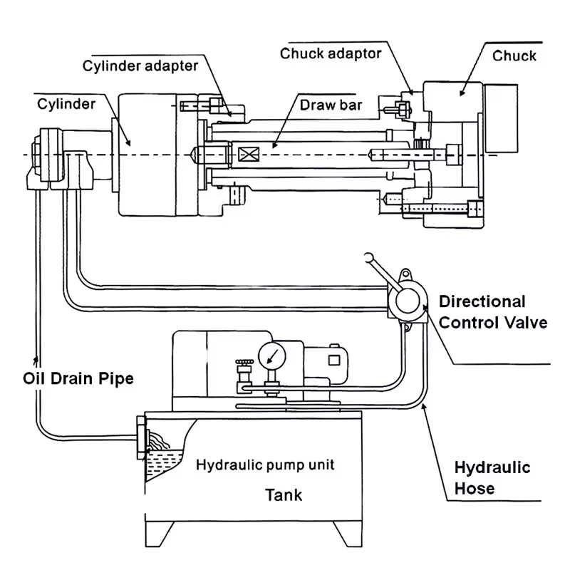
For hydraulic power chuck systems, the front chuck mounting should not be reviewed separately from the rear-side rotary cylinder and drawbar or draw tube connection.
Important review items include rotary cylinder type, drawbar or draw tube connection, actuator stroke, rear clearance, through-hole requirement and whether the chuck reaches the intended open and closed positions.
For the system principle, see hydraulic power chuck and rotary cylinder system. For product matching, see the rotary hydraulic cylinder page.
Runout Checks After Mounting
After mounting, runout should be checked at the correct measurement point and datum. A runout result may be affected by mounting face condition, adapter plate accuracy, spindle nose condition, chuck body location, jaw contact and the workpiece datum.
If runout is not acceptable, do not judge only the chuck body. Review the mounting stack from the spindle side to the jaws and workpiece.
For more detail, see power chuck runout and clamping accuracy.
Common Mistakes
Common mistakes include using a torque value without confirming bolt grade, treating the reference table as a universal installation standard, ignoring the mounting face, reusing unsuitable bolts, checking only the chuck body but not the adapter plate, and judging runout without checking the measurement datum.
Another common mistake is replacing a chuck by outside diameter only. Power chuck replacement should also consider spindle nose, adapter plate, drawbar or draw tube, rotary cylinder and jaw setup.
What Information to Prepare Before Mounting Review
Before asking for power chuck mounting review, prepare:
- Machine brand and model
- Spindle nose type
- Existing chuck model and size
- New chuck model and size
- Adapter plate or back plate drawing
- Bolt size and quantity
- Known bolt grade, if available
- Mounting hole pattern
- Locating diameter and face contact information
- Rotary cylinder model
- Drawbar or draw tube data
- Required through-hole condition
- Jaw type and jaw layout
- Workpiece drawing and clamping diameter
- Runout or repeatability requirement if already specified by the project
- Photos of the spindle face, adapter plate and rear actuator area if available
Related Power Chuck Resources
For replacement data, start with power chuck mounting interface and drawbar data. For measurement after installation, see power chuck runout and clamping accuracy. If a symptom already exists, use power chuck troubleshooting checks as a review map.
For the actuator path, see hydraulic power chuck and rotary cylinder system. For front-side movement checks, see jaw stroke and clamping range. For the broader category, see the power chuck overview and soft jaw forming methods.
Related Resources
FAQ
Why does bolt torque matter when mounting a power chuck?
Bolt torque affects how the chuck or adapter plate is held against the mounting face. It should be checked together with bolt size, bolt grade, thread condition, adapter plate design and machine builder requirements.
Can wrong bolt torque cause runout?
Incorrect or unsuitable bolt tightening can affect the mounting result, but runout can also come from the mounting face, adapter plate, spindle nose, chuck locating surface, jaw contact or workpiece datum.
Can I use one torque value for all power chucks?
No. Torque depends on bolt size, bolt grade, thread condition, lubrication condition, chuck design and machine requirements. A reference table should not be used as a universal rule.
What should be checked before tightening chuck mounting bolts?
Check the mounting face, spindle nose, adapter plate, locating diameter, bolt pattern, mounting holes, bolt size, bolt condition and supplier instructions before tightening the chuck mounting bolts.
Is adapter plate accuracy important for power chuck mounting?
Yes. The adapter plate connects the spindle side and the chuck side. Its locating diameter, face contact, bolt pattern and machining quality can affect the final mounting result.
Should I check the rotary cylinder before mounting the chuck?
For hydraulic power chuck systems, the rotary cylinder, drawbar or draw tube, actuator stroke, rear clearance and through-hole requirement should be reviewed together with the front chuck mounting.
What information is needed for power chuck mounting review?
Prepare the machine model, spindle nose, chuck model, adapter plate drawing, bolt size, bolt grade if known, rotary cylinder model, drawbar data, jaw layout and workpiece drawing.
Should the torque table replace machine builder instructions?
No. A torque table is only a reference. Final tightening torque should follow the bolt supplier, chuck supplier, machine builder and project engineering requirements.