A 21-Inch Hydraulic Chuck Shipped to Chile This Week
This 21-inch chuck is on its way to Chile
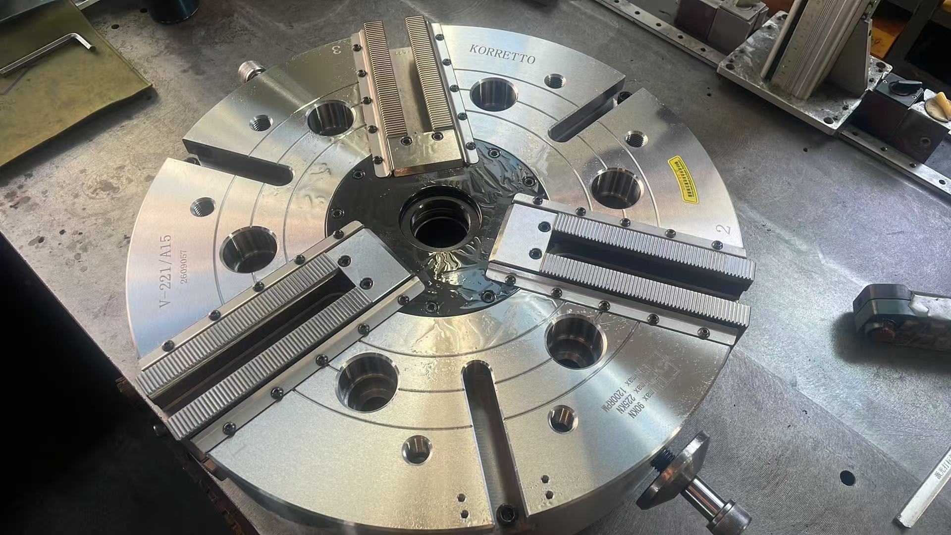
We shipped this 21-inch hydraulic chuck to a customer in Chile this week. The photo was taken in our workshop and shows the actual chuck. You can see the three master jaws, their serrations and the mounting holes. Here is a closer look at what matters when fitting a chuck of this size.
What you can see in the photo
The three master jaws run radially across the chuck face. Matching top jaws mount on their serrated faces; those top jaws are the parts that grip the workpiece. Their serrations, bolt holes and mounting positions need to match the master jaws. Chuck size alone does not tell you which jaws will fit.
Three-jaw hydraulic chucks are commonly used for round bars, discs, shafts and sleeves. A through-hole chuck is an option when stock needs to pass through the spindle. A solid chuck suits jobs without through feeding, such as individual blanks and discs. The product links below let you compare these arrangements.
Choose the jaws for the part
Choose the jaws around where the part is held, how much contact it needs and where the cutting tool must reach. Soft jaws can be machined to fit an outside diameter or locating profile. Hard jaws serve the corresponding gripping jobs. Start with the part drawing and master-jaw connection, then choose the jaw shape.
For a disc or short part, decide which diameter to grip, which face to use as the axial stop and which surfaces to machine. For longer parts, also plan the overhang and support. The jaws need enough contact with the part while leaving the tool path clear.
How the cylinder drives the chuck
A hydraulic chuck is usually driven by a rotary cylinder behind the spindle, connected through a drawbar or drawtube. The cylinder pushes or pulls along the spindle axis; the chuck mechanism moves the jaws in and out. Cylinder force, stroke, connecting threads and allowable chuck input therefore need to be checked together.
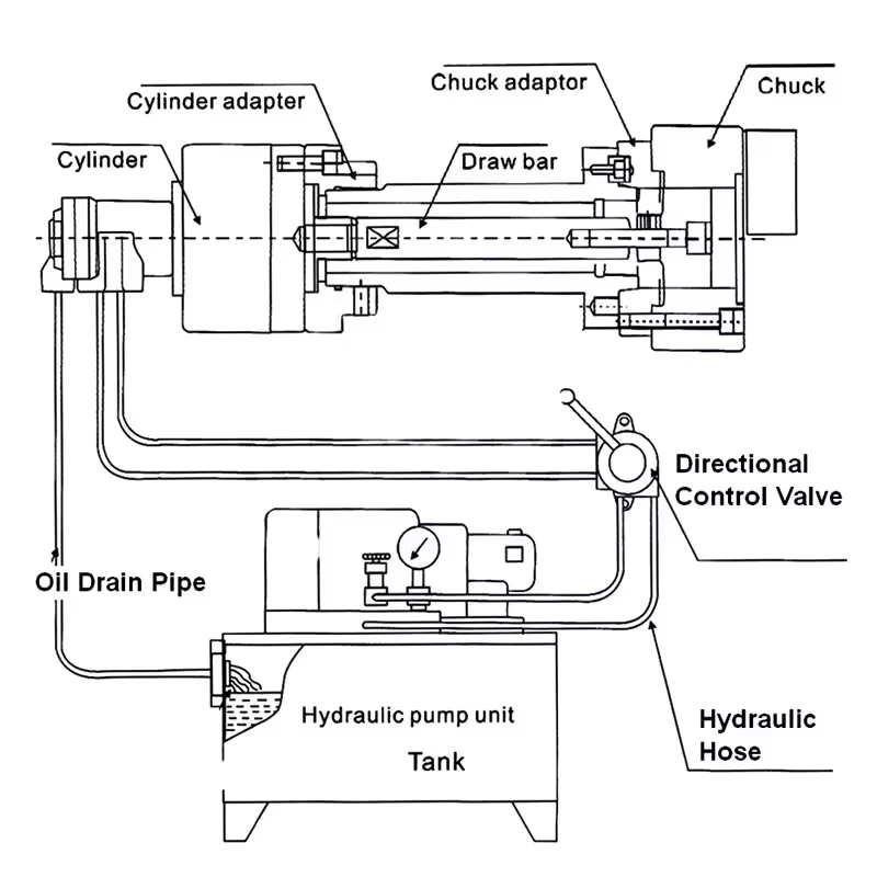
The diagram shows how these parts connect. Oil pressure, drawbar force and jaw gripping force are different quantities. Set up the grip for the workpiece and cutting operation, and take jaw weight, gripping height and operating speed into account.
What to check on the machine
With a large chuck like this 21-inch unit, check the spindle connection, mounting dimensions, spindle load capacity and space inside the machine. Allow room to load the part and open the jaws. Check that the tool can reach every intended cut without touching the jaws or nearby machine parts.
Need a similar chuck?
Looking for a similar hydraulic chuck? Send us your machine model, spindle details and workpiece drawing. Include the existing cylinder and drawbar information if you have it, plus the jaw requirements and machining operations. That gives us a useful starting point for discussing the right arrangement.