2026-06-19 · Workholding Guide
What Is an Indexing Chuck? Working Principle, Types and CNC Applications
An indexing chuck is a chuck-based workholding unit that clamps a workpiece and rotates it to fixed angular positions without removing the part from the machine. In CNC lathe workholding, it is often used for valve bodies, tees, elbows, cross-shaft parts and other components that need machining from more than one direction.
The main value of an indexing chuck is not only rotation. It keeps the workpiece in one controlled clamping system, indexes it to a defined angle, locks the position, and then allows the next machining step to begin. This can reduce repeated manual setup and help maintain a more consistent relationship between several machined features.
For KORRETTO indexing chuck applications, hydraulic clamping and hydraulic indexing are the main working method. Common indexing arrangements include 45° × 8 positions or 60° × 6 positions, depending on the chuck structure and workpiece requirement. Final selection should still be confirmed by drawing, machine interface, workpiece weight, cutting direction and machining sequence.
What is an indexing chuck?
An indexing chuck is a spindle-side chuck that combines clamping and angular positioning. A standard chuck mainly opens, closes and holds the part. An indexing chuck adds another function: after the workpiece is clamped, the chuck can rotate or index the part to a preset angular position.
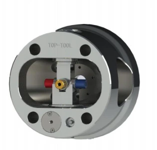
This makes it useful when several machining directions are required in one setup. Instead of removing the workpiece, turning it by hand and clamping it again, the machine can complete a sequence such as clamp, machine, unlock, index, lock, machine again and then unload.
Indexing chucks are commonly considered for:
- valve bodies with several ports;
- tee and elbow fittings;
- cross-shaft or intersecting-axis parts;
- multi-angle workpieces;
- parts where repeated manual re-clamping causes positioning variation;
- CNC lathe processes that need several angular machining positions.
For a broader product overview, see the KORRETTO indexing chuck series.
How does an indexing chuck work?
An indexing chuck works through a coordinated sequence of clamping, hydraulic indexing and mechanical locking. The exact structure depends on the model, but the basic process is usually similar.
First, the chuck clamps the workpiece. Then, when the machining program requires another angular position, the system releases the indexing lock, rotates the chuck to the next position, confirms the position, locks the chuck mechanically, and then allows machining to continue.
In a hydraulic auto indexing chuck system, two hydraulic functions are typically required:
| Function | Purpose | Typical control point |
|---|---|---|
| Clamping and unclamping | Holds or releases the workpiece | Hydraulic pressure controlled by a valve |
| Indexing movement | Rotates the chuck to the next position | Hydraulic indexing circuit |
| Mechanical locking | Holds the indexed angle during cutting | Locking mechanism and position confirmation |
| Position signal | Confirms the chuck state to the machine | Detection signal connected to the machine control |
This is why an indexing chuck should not be treated as only a rotating chuck body. It is a workholding system that needs the chuck, hydraulic supply, oil distribution, signal logic and machine program to work together.
Main components in a hydraulic indexing chuck system
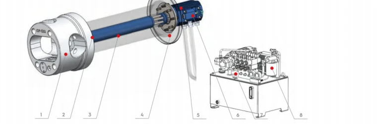
A typical hydraulic indexing chuck system may include the indexing chuck, front flange, telescopic connecting rod, rear flange, distributor, oil pipe assembly, lock alarm or position detection mechanism, and hydraulic station.
Main components and their functions
| No. | Component | Function |
|---|---|---|
| 1 | Indexing Chuck | Provides workpiece support and indexing. |
| 2 | Front Flange | Connects the spindle nose to the indexing chuck. |
| 3 | Telescopic Connecting Rod | Connects the chuck and distributor oil channels. |
| 4 | Rear Flange | Connects the distributor to the rear end of the lathe bed. |
| 5 | Distributor | Distributes and supplies oil flow during rotation. |
| 6 | Chuck Lock Alarm Mechanism | Provides position detection signals at 45° and 90°. |
| 7 | Oil Pipe Assembly | Connects the distributor and hydraulic station oil channels. |
| 8 | Hydraulic Station Optional | Supplies clamping support force and indexing pressure. |
The front flange connects the chuck to the spindle nose. The rear flange and distributor are installed behind the spindle or at the rear side of the lathe structure. A telescopic stainless-steel connecting pipe or rod links the chuck-side oil circuit to the distributor. The distributor supplies oil during rotation, while the hydraulic station provides pressure for clamping and indexing.
The system generally requires two hydraulic circuits: one for clamping and unclamping, and one for indexing. These circuits are controlled by solenoid valves. Position and locking signals are then connected to the machine control so the chuck can work as part of the machining cycle.
In many retrofit or application projects, the machine ladder program may need to be modified. This can be handled by the machine builder, by the customer's electrical team, or with technical support from the workholding supplier.
For the product-level page, see the KORRETTO hydraulic auto indexing chuck.
Common indexing angles
Common indexing arrangements include 45° × 8 positions and 60° × 6 positions. These are suitable for many valve, fitting and multi-port components where the workpiece needs to be presented to the tool at fixed angular intervals.
The right indexing angle depends on:
- the number of machining directions;
- the port or bore layout;
- the required relationship between machined features;
- tool access;
- chuck locking structure;
- machine control sequence;
- available space around the workpiece.
The indexing angle should be selected from the actual part drawing and process plan. It should not be chosen only from a catalog value.
Indexing chuck applications on CNC lathes
The main application for an indexing chuck is CNC lathe workholding. In valve machining, many workpieces are cast or forged blanks with several ports and irregular outside shapes. If the workpiece is clamped several times, each setup can introduce positioning variation.
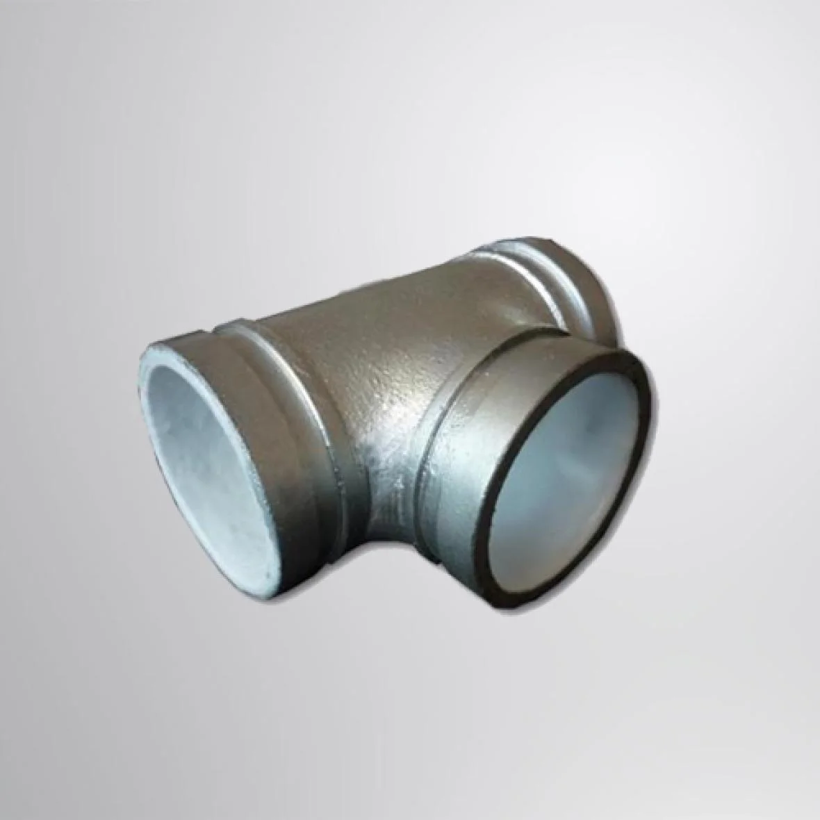
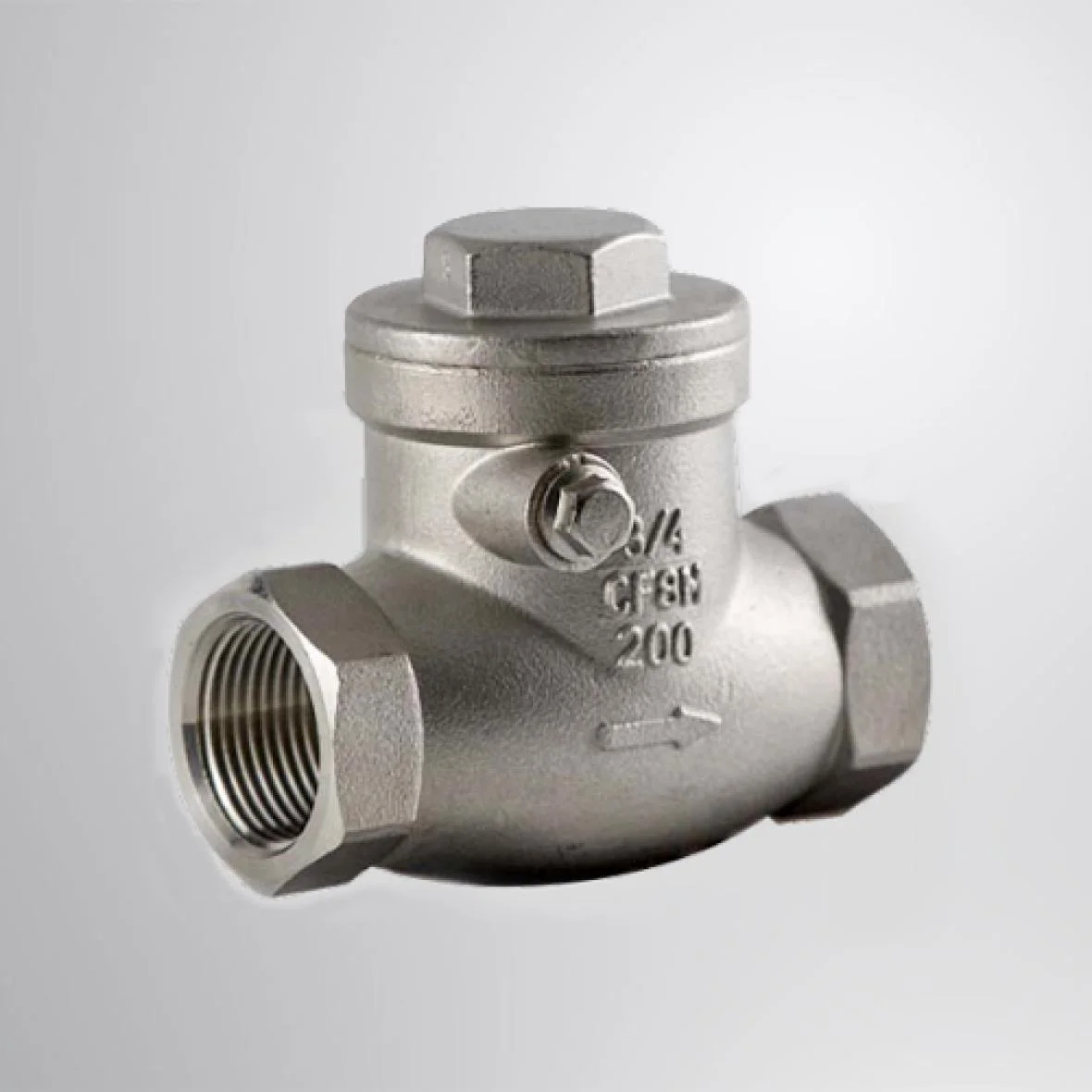
An indexing chuck allows the workpiece to stay in one clamping system while different faces or ports are machined. This is useful for valve bodies, tee fittings, elbow fittings and cross-shaped components.
Traditional valve machining often uses one of two routes. One route is a special-purpose machine, where the workpiece stays fixed and several boring tools rotate at the same time. This can be fast, but the process may be less flexible and the bore or surface quality depends heavily on the dedicated setup. Another route is multi-step machining on a lathe, where the part is clamped, machined, removed, rotated and clamped again. This can be more flexible, but repeated clamping can reduce efficiency and make coaxial relationships harder to maintain.
An indexing chuck combines some advantages of both approaches. It keeps the flexibility of lathe machining while reducing repeated manual positioning. It is especially useful when the part family is repeated and the machining angles are known.
Examples of multi-angle workpieces
The following examples show typical workpieces where indexing chuck workholding may be reviewed.
For more application examples, see Indexing Chuck in the Valve Industry and Indexing Chuck for Multi-Angle Workpieces.
Indexing chuck vs rotary table
An indexing chuck and a rotary table both position a workpiece by angle, but they are not the same type of workholding.
| Item | Indexing chuck | Rotary table |
|---|---|---|
| Machine position | Usually mounted on the spindle side of a CNC lathe | Usually mounted on the table side of a milling machine or machining center |
| Main function | Clamping plus angular indexing | Workpiece or fixture positioning by table rotation |
| Typical use | Valve bodies, fittings, multi-angle turning operations | Milling, drilling, slotting, circular positioning |
| Clamping role | Chuck holds the workpiece directly or through jaws | Usually needs a fixture, vise or chuck mounted on the table |
| Selection focus | Chuck size, clamping force, indexing angle, hydraulic control, spindle interface | Table size, load capacity, indexing accuracy, fixture layout |
A rotary table can be a good solution for milling or drilling setups. An indexing chuck is more suitable when the workpiece needs to be held and indexed on the lathe spindle side.
For machine tool accessories, see KORRETTO dividing heads and rotary tables.
Suitable and less suitable applications
An indexing chuck is suitable when the workpiece has repeated geometry, known indexing positions and enough contact area for stable clamping. It is also suitable when the process needs better consistency than repeated manual re-clamping can provide.
It is commonly reviewed for:
- valve body machining;
- elbow and tee fitting machining;
- cross-shaft or intersecting-axis parts;
- multi-port components;
- batch production with repeated angles;
- CNC lathe applications that need automatic indexing.
It may be less suitable when the workpiece is a one-off part, when the casting surface varies too much, when the part is too heavy for the available spindle and chuck system, or when the tool path cannot clear the chuck body and jaws. It may also be less suitable if the machine cannot support the required hydraulic circuits, position signals or control logic.
For special workholding solutions, see application-specific power chucks and What Is a Power Chuck?.
Indexing chuck catalog dimensions and parameters
The catalog tables below are useful for preliminary comparison between TK indexing chuck models. Dimensions are listed in mm according to the catalog table. Catalog values are used for preliminary model comparison. Final selection should be checked with the actual workpiece, jaws, spindle interface and machine conditions.
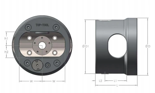
Indexing chuck model and dimension references
| Model | D | D1 | L | L1 | L2 | W |
|---|---|---|---|---|---|---|
| TK-168 | 190 | 168 | 142 | 70 | 35 | 68 |
| TK-203 | 216 | 203 | 158 | 82 | 36 | 36 |
| TK-225 | 240 | 225 | 170 | 95 | 37 | 37 |
| TK-256 | 276 | 256 | 187 | 105 | 42 | 42 |
| TK-305 | 330 | 305 | 212 | 130 | 45 | 45 |
| TK-400 | 416 | 400 | 278 | 175 | 58 | 58 |
| TK-460 | 490 | 460 | 308 | 205 | 58 | 58 |
| TK-570 | 570 | 429 | 193.5 | 105 | 250 | |
| TK-680 | 680 | 484 | 239 | 310 | 300 | |
| TK-850 | 850 | 617 | 299 | 380 | 375 | |
| TK-1000 | 1000 | 748 | 339 | 450 | 420 | |
| TK-1200 | 1200 | 948 | 439 | 650 | 530 |
Indexing chuck catalog parameters
| Model | Max. Workpiece Size [mm] | Clamping Force [kN] | Clamping Stroke [mm] | Max. RPM | Net Weight [kg] |
|---|---|---|---|---|---|
| TK-168 | 136 | 10.6 | 9 | 70 | 15 |
| TK-203 | 164 | 11.3 | 15.2 | 82 | 24 |
| TK-225 | 190 | 11.3 | 15.2 | 95 | 30 |
| TK-256 | 210 | 14.5 | 19.1 | 105 | 42 |
| TK-305 | 260 | 14.5 | 19.1 | 130 | 61 |
| TK-400 | 350 | 31.4 | 30 | 175 | 120 |
| TK-460 | 410 | 31.4 | 30 | 205 | 161 |
| TK-570 | 460 | 56.5 | 42 | 1200 | 306 |
| TK-680 | 560 | 56.5 | 42 | 1000 | 412.6 |
| TK-850 | 720 | 66.3 | 55 | 800 | 660.6 |
| TK-1000 | 860 | 80.0 | 65 | 500 | 1298 |
| TK-1200 | 1060 | 80.0 | 65 | 500 | 1558 |
Catalog parameters to check before selection
| Parameter | What it means for selection |
|---|---|
| Max. Workpiece Size | Helps check whether the valve body, fitting or multi-angle workpiece can fit the chuck range. |
| Clamping Force | Used to evaluate whether the workpiece can be supported during cutting. |
| Clamping Stroke | Affects loading clearance, opening range and workpiece size compatibility. |
| Max. RPM | Must be checked with the actual chuck, jaws, workpiece and machine conditions. |
| Net Weight | Affects spindle load, installation review and machine compatibility. |
What information is needed for an indexing chuck review?
An indexing chuck should be reviewed as a complete workholding system. The chuck model alone is not enough.
Before selecting a solution, it is useful to provide:
- workpiece drawing;
- material and casting condition;
- workpiece weight and maximum outside size;
- datum surface or datum bore;
- number of required indexing positions;
- required indexing angle;
- machining sequence;
- cutting direction and tool access;
- machine model and spindle nose;
- available hydraulic pressure and oil circuits;
- whether ladder program or machine signal integration is possible;
- required batch size and cycle expectation.
For large-diameter applications, the chuck body, workpiece weight, spindle capacity, hydraulic supply and locking structure should be reviewed carefully. KORRETTO can review large indexing chuck applications according to the actual workpiece and machine conditions.
Related KORRETTO pages
FAQ
What is an indexing chuck?
An indexing chuck is a chuck-based workholding unit that clamps a workpiece and rotates it to fixed angular positions. It is used when a part needs machining from several directions without being removed and manually re-clamped each time.
How does an indexing chuck work?
A hydraulic indexing chuck typically clamps the workpiece, releases the indexing lock, rotates to the next position, locks mechanically, confirms the position signal and then allows the next machining step. The exact sequence depends on the chuck, hydraulic circuit and machine control.
What indexing angles are commonly used?
Common indexing arrangements include 45° × 8 positions and 60° × 6 positions. The correct angle depends on the workpiece drawing, port direction, machining sequence and chuck structure.
Is an indexing chuck mainly used on CNC lathes?
Yes. Most KORRETTO indexing chuck applications are designed for CNC lathe spindle-side workholding. Indexing chuck concepts can also appear in machining center applications, but lathe valve and fitting machining is the main use case.
How is an indexing chuck different from a rotary table?
An indexing chuck is mounted on the spindle side and directly clamps the workpiece. A rotary table is usually mounted on a machine table and positions a fixture or workpiece from below. They solve different workholding problems.
What information is needed to review an indexing chuck application?
A review usually needs the workpiece drawing, material, weight, machining sequence, indexing angles, machine model, spindle interface, hydraulic supply, position signal requirements and expected production quantity.